FrameSaver DSL
Copyright 2002 Paradyne Corporation All rights reserved
Contents
Configuration Options
Configuration Procedures
Security and Logins
Configuring the FrameSaver DSL Router
December
Access Levels Command Modes Changing Access Levels
Viewing LMI Captured Packets from the User Interface
Troubleshooting
Setting Up Network Health for FrameSaver Device
Snmp MIBs, Traps, and Rmon Alarm Defaults
Menu Hierarchy
Router CLI Commands, Codes, and Designations
Router Command Line Summaries and Shortcuts
Connectors, Cables, and Pin Assignments
Index
Technical Specifications Equipment List
About This Guide
Purpose and Intended Audience
Document Organization
Technical Manuals → Technical Glossary
Concord Communications Documentation
Product-Related Documents
Document Number Document Title
NetScout Documentation
Xxxxxxxxxxxx
Conventions Used
Convention Interpretation
X.x
System Overview
About FrameSaver DSL Devices
FrameSaver DSL Features
CSU/DSU-Specific Features
Router-Specific Features
About FrameSaver DSL Devices
Diagnostic Feature Set
Diagnostic Feature Set
Advanced SLM Feature Set
Model # Product PVCs
Advanced SLM Feature Set
Customer Premises HQ Site
Network Configuration Examples
Access Network
Remote Site
Central Office Customer Premises
Access
OpenLane SLM System
OpenLane Features
About FrameSaver DSL Devices December
User and Command Line Interfaces Basic Operation
Logging On
If your login was Then
Ending a Session
Procedure
Select
Main Menu
Screen Format Description
Screen Work Areas
Navigating Menu-Driven User Interface Screens
Keyboard Keys
Press
Function Keys
Selecting from a Menu
For the screen Select Function Press Enter to
Switching Between Screen Areas
Selecting a Field for Input
Device Name MyDeviceName
CLI Keyboard Keys
Navigating the Router’s CLI
9700-A2-GB20-20
Configuration Procedures
Configuration Edit/Display Menu
Basic Configuration From the User Interface
Configuration Option Area Description
Configuration Option Areas
Main Menu Configuration
Accessing and Displaying Configuration Options
Changing Configuration Options
Saving Configuration Options
Configuration PVC Connections
Configuration Procedures
Configuration Options
Configuration Options
Using the Easy Install Feature
Main Menu Easy Install
Easy Install Screen
Easy Install Configuration Options 1
Ethernet Management Options Screen
Easy Install Configuration Options 2
Network 1 DSL Line Rate Mode
Create a Dedicated Network Management Link
784
Easy Install Configuration Options 3
Network 1 DSL Line Rate
384
Easy Install Configuration Options 4
Network 1 Channel
Port-1 Port Type 9788 CSU/DSU
Main Menu Control System Information
Entering System Information and Setting the System Clock
Changing the Operating Mode
Main Menu Control Change Operating Mode
Configuration Option Tables
Configuring the Overall System
Configuring Frame Relay and LMI for the CSU/DSU
Main Menu Configuration System Frame Relay and LMI
LMI Error Event N2
CSU/DSU Frame Relay and LMI Options 2
LMI Clearing Event N3
LMI Heartbeat T1 Possible Settings 5, 10, 15, 20, 25
CSU/DSU Frame Relay and LMI Options 3
LMI Status Enquiry N1
Configuring Class of Service Definitions
Main Menu Configuration System Class of Service Definitions
Field Setting After RfcCodePoints Selected
Code Points Assigned
Class of Service Definitions
Class of Svc Name
Measure Latency & Availability
Name
Code Point Definitions
Code Point Definitions
Code Pnt
SLV Sample Interval secs
Configuring Service Level Verification Options
Main Menu Configuration System Service Level Verification
Service Level Verification Options 1
SLV Delivery Ratio
Service Level Verification Options 2
SLV Type Available Settings Standard, COS 1-COS
Dlci Down on SLV Timeout
Service Level Verification Options 3
Configuring General System Options
Main Menu Configuration System General
Test Duration min
Operating Rate Possible Settings AutoRate, 64, 128
Configuring Network Interfaces
Configuring the Network Physical Interface
Main Menu Configuration Network Physical
Line Rate Mode Possible Settings Hunt, AutoRate, Fixed
Network Physical Interface Options
DSL Line Rate Kbps
Region
Line Rate Mode
776, 784, 1544
2056
Main Menu Configuration Network Dlci Records
Configuring Frame Relay for the Network Interface
Configuring Dlci Records for the Network Interface
Main Menu Configuration Network Frame Relay
Dlci Number
Configuring Circuit Records for the Network Interface 9783
Main Menu Configuration Network Circuit Records
11. Circuit Records Options 1
Committed Burst Size Bc Bits
11. Circuit Records Options 2
CIR bps
9783 0 9788 0
Outbound Management Priority
11. Circuit Records Options 3
Excess Burst Size Be Bits
9783 9788
Cell Payload Scrambling
Configuring ATM for the Network Interface 9783
Main Menu Configuration Network ATM
Cell Delineation Error Event Threshold
13. CSU/DSU Data Port Physical Interface Options 1
Configuring the User Data or Virtual Router Port
Configuring the CSU/DSU’s Data Port Physical Interface
Main Menu Configuration Data Ports Physical
Monitor DTR
13. CSU/DSU Data Port Physical Interface Options 2
Transmit Clock Source
Monitor RTS Control
LMI
Configuring Frame Relay on the CSU/DSU’s Data Port
Main Menu Configuration Data Ports Frame Relay
14. CSU/DSU Frame Relay Options 1
14. CSU/DSU Frame Relay Options 2
Reserved. Entry of an
Configuring Dlci Records
Main Menu Configuration Network Dlci Records Data Ports
Frame relay interface. Dlci
9720 0 9783 0 9788 0
15. Dlci Records 2
15. Dlci Records 3
9720
Dlci Priority
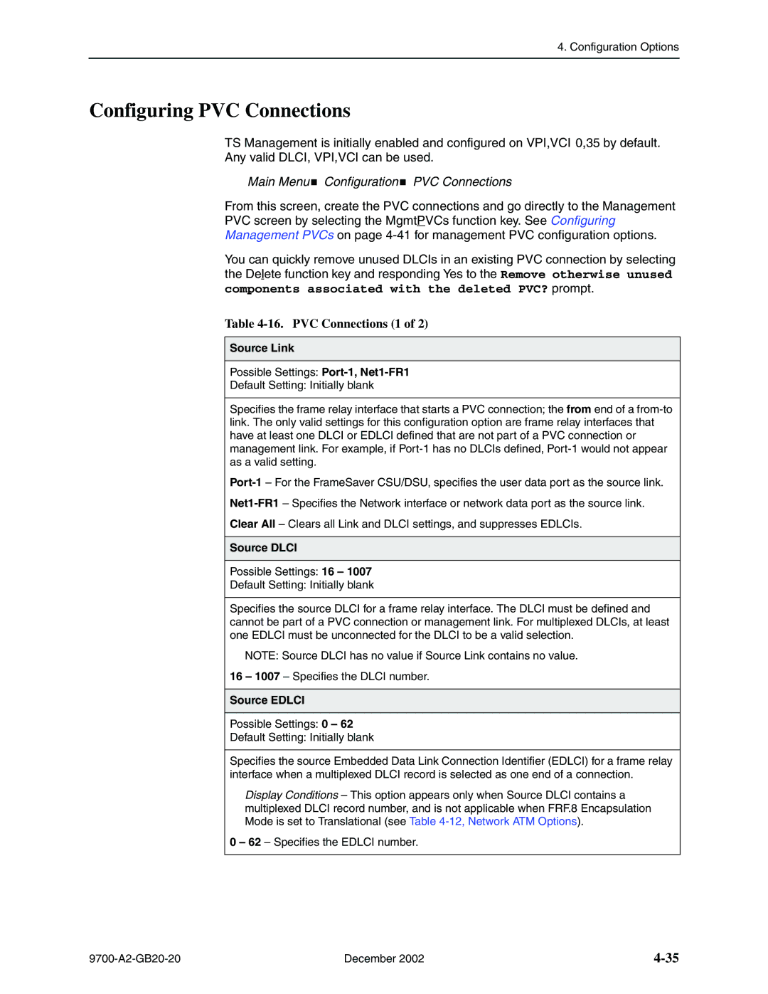
Configuring PVC Connections
Main Menu Configuration PVC Connections
16. PVC Connections 1
Destination Edlci
16. PVC Connections 2
Destination Link
Destination Dlci
Configuring the IP Path List
Main Menu Configuration IP Path List Static
17. IP Path List
Setting Up Management and Communication
Configuring Node IP Information
Management Link
18. Node IP Options 1
TS Access Management Link
18. Node IP Options 2
Management MTU Size
Components associated with the deleted PVC?
Configuring Management PVCs
Payload Managed
19. Management PVC Options 1
19. Management PVC Options 2
Set DE
Primary Dlci
VPI 0 VCI 32
19. Management PVC Options 3
Primary Edlci
Primary VPI,VCI Number
Encapsulation
19. Management PVC Options 4
Snmp Management
Configuring General Snmp Management
Name 1 Access
20. General Snmp Management Options 1
20. General Snmp Management Options 2
Name 2 Access
Telnet Session
Configuring Telnet and/or FTP Sessions
Telnet Login Required
21. Telnet and FTP Session Options 1
FTP Session
Inactivity Timeout
21. Telnet and FTP Session Options 2
Disconnect Time Minutes
9720 1 9783 1 9788 1
FTP Login Required
21. Telnet and FTP Session Options 3
FTP Max Transfer Rate Kbps
Number of Managers
Configuring Snmp NMS Security
22. Snmp NMS Security Options 1
NMS IP Validation
22. Snmp NMS Security Options 2
Access Type
Number of Trap Managers
Configuring Snmp Traps
23. Snmp Traps Options 1
Snmp Traps
Enterprise Specific Traps
23. Snmp Traps Options 2
Link Traps Interfaces
Link Traps Possible Settings Disable, Up, Down, Both
Possible Settings Network, Ports, All, None
23. Snmp Traps Options 3
IP SLV Availability Traps
23. Snmp Traps Options 4
Rmon Traps
Latency Traps
Configuring Ethernet Management
24. Ethernet→Management→Options 1
Status
Proxy ARP
24. Ethernet Management Options 2
Character Length
Configuring the Communication Port
25. Communication→ Port→Options 1
Port Use
Ignore Control Leads
Login Required
25. Communication Port Options 2
Stop Bits
25. Communication Port Options 3
RIP
25. Communication Port Options 4
26. External Modem COM Port Options
Configuring the COM Port to Support an External Modem
Main Menu Configuration Management and Communication
External Modem Com Port→
Configuration Options December
NAT and Napt Configuration Example
Configuring the FrameSaver DSL Router
FrameSaver DSL Router Overview
DSL Network Interface
Ethernet
Address Resolution Protocol
IP Routing
Proxy ARP
Interface Configuration
Network Address Translation
IP Options Processing
Applications Supported by NAT
NAT Mapping Public IP Addresses Private IP Addresses
NAT Configuration Example
Save exit
Napt Configuration Example
Network Address Port Translation
Napt Mapping Public IP Address Private IP Addresses
Access-list 1 permit 10.1.3.0
Ip nat inside source list 1 interface se 0.x overload
Int ethernet 0 ip nat inside int serial 0.x ip nat outside
Ip nat inside source static 10.1.1.1
NAT and Napt Configuration Example
Dynamic Host Configuration Protocol Server
Dhcp Server with NAT Configuration Example
Public IP Addresses for NAT Private IP Addresses
NAT
Dhcp Relay Agent
Dhcp Server at Remote Site Configuration Example
DSL
Dhcp Relay Configuration Example
Ip dhcp server Ip route 155.1.3.254 serial
Dhcp LAN
IP Router Filtering Bridge Filtering
Router Security
NAT DSL
IP Filtering
Land Bug Prevention
Smurf Attack Prevention
Diagnostics ATM Ping D-C
Verifying the End-to-End Management Path
Provisioning the Router Interface
Configuring the Router Using Terminal Emulation
Security and Logins
FTP Snmp
Limiting Access
Set the configuration option
Controlling Asynchronous Terminal Access
Controlling External COM Port Device Access
Controlling Telnet and FTP Access
External Modem Com Port
See Creating a Login for the User Interface on
Limiting Telnet Access
FTP
Limiting FTP Access
Limiting Telnet or FTP Access Over the TS Management Link
Disabling Snmp Access
Controlling Snmp Access
Assigning Snmp Community Names and Access Levels
See Configuring→General Snmp →Management in , Configuration
Limiting Snmp Access Through IP Addresses
Controlling Router CLI Access
Access Levels Command Modes
Largo
Page
Field Enter
Creating a Login for the User Interface
Main Menu Control Administer Logins
Security in , Configuration Options
Modifying a Login
Deleting a Login
Example
Operation and Maintenance
Displaying Identity System Information
Main Menu Status Identity
View this field To find
Viewing LEDs and Control Leads
Main Menu Status Display LEDs and Control Leads
Label Indication Color What It Means
LED Descriptions
Display LEDs & Control Leads Screen for a 9783 Router
LED Descriptions 1
Port LED CSU/DSU
Control Lead Descriptions
LED Descriptions 2
Network LEDs
Control Leads Label Indication What It Means
Terminal
Device Messages
Device Messages 1 What It Indicates What To Do
Seen at an FTP
Software. See Activating Software
Device Messages 2 What It Indicates What To Do
Device Messages 3 What It Indicates What To Do
See Upgrading System
Device Messages 4 What It Indicates What To Do
COM Port usage field
Device Messages 5 What It Indicates What To Do
Router CLI Messages
CLI Messages 1 What It Indicates
MaximumDHCPClients
Start-ip-address or end-ip-address
CLI Messages 2 What It Indicates
Either pool or interface, and overload are
CLI Messages 3 What It Indicates
CLI Messages 4 What It Indicates
CLI Messages 5 What It Indicates
Status Menu
Status Information
Main Menu Status System and Test Status
Last Reset
System and Test Status Messages
Self-Test Results Messages
Health and Status Messages 1 What It Indicates
Health and Status Messages
InterfaceDLCInnnn
Health and Status Messages 2 What It Indicates
Atmlink
PathIP Address Down
Main Menu Status IP Path Connection Status
IP Path Connection Status
Test Status Messages
Test Status Messages What It Indicates
This is the IP address
IP Path Connection Status Screen Example
IP Path Connection Status
FR Link Net1-FR1, Port-1 Frame relay link
Field Display What It Indicates
PVC Connection Status
PVC Connection Status Screen Example
PVC Connection Status Screen 1
Edlci
PVC Connection Status Screen 2
Network Interface Status
Main Menu Status Network Interface Status
Network Interface Status Screen Example
IP Routing Table Screen Example
IP Routing Table Management Traffic
TTL
11. IP Routing Table Values Field What It Indicates
Performance Statistics
Main Menu Status Performance Statistics
Performance Statistics Menu
13, SLV Performance Statistics for IP Enabled Dlci
Service Level Verification Performance Statistics
Inbound Dropped
Dlci connection
COS ID
Service Definitions in , Configuration Options
CIR&EIR
Dlci Performance Statistics
Main Menu Status Performance Statistics Dlci
14. Dlci Performance Statistics 1 Field What It Indicates
14. Dlci Performance Statistics 2 Field What It Indicates
Additional Performance Statistics for IP Enabled Dlci
Frame Relay Link
Frame Relay Errors
Frame Relay Performance Statistics
16. Frame Relay Performance Statistics 1 What It Indicates
Frame Relay Hdlc Errors
16. Frame Relay Performance Statistics 2 What It Indicates
Frame Relay LMI CSU/DSUs only
AAL5 ATM Adaption Layer
OAM Operations, Administration, and Maintenance
ATM Performance Statistics 9783
17. ATM Performance Statistics What It Indicates
VCC Virtual Channel Connection
VCC Performance Statistics 9783
Main Menu Status Performance Statistics VCC
18. VCC Performance Statistics 1 What It Indicates
19. Shdsl Line Performance Statistics What It Indicates
Shdsl Line Performance Statistics
18. VCC Performance Statistics 2 What It Indicates
Main Menu Status Performance Statistics XDSL Line
Ethernet Performance Statistics
Main Menu Status Performance Statistics Ethernet
20. Ethernet Performance Statistics What It Indicates
→ →Ethernet
Clearing Performance Statistics
Function key Main Menu
Frame Relay
Trap Event Log Screen Example
Trap Event Log
FTP File Transfers
Initiating an FTP Session
Command Definition
If the message displayed is Then
Upgrading System Software
Determining Whether a Download Is Completed
Activating Software
Main Menu Control Select Software Release
Transferring Collected Data
If retrieving Then
Main Menu Control LMI Packet Capture Utility
Troubleshooting
Main Menu Status Display LEDs and Control LEDs
Problem Indicators
Indicators See
Device Messages in , Operation and Maintenance
Resetting the Unit and Restoring Communication
Resetting the Unit from the Control Menu
Resetting the Unit By Cycling the Power
If selecting Following occurs
Restoring Communication with an Improperly Configured Unit
Troubleshooting Management Link Feature
LMI Packet Capture Utility Feature
Main Menu Control LMI Packet Capture Utility
LMI Trace Log Example
Viewing LMI Captured Packets from the User Interface
Telnet
Control Telnet
Telnet Example
Alarm Conditions 1 What It Indicates What To Do
Alarms
IPAddress
Alarm Conditions 2 What It Indicates What To Do
CSU/DSU only minor Alarm
Only minor alarm
Alarm Conditions 3 What It Indicates What To Do
Down minor alarm
PathIP Address
Viewing the Trap Event Log
Troubleshooting Tables
Device Problems Symptom Possible Cause Solutions
Device Problems
ATM Problems Symptom Possible Cause Solutions
ATM Problems
Frame Relay PVC Problems Symptom Possible Cause Solutions
Frame Relay PVC Problems
Tests Available
CSU/DSU Test Menu Example
Router Test Menu Example
Test Timeout Feature
Aborting All Tests
Starting and Stopping a Test
PVC Tests Screen Example
PVC Tests
Main Menu Test Data Port PVC Tests
PVC Loopback
Send Pattern
Main Menu Test Network PVC Tests
When 5 frames out of 25 are missing or out of sequence
Monitor Pattern
To run a connectivity test on a link
Network ATM Loopback Tests Screen Example
Network ATM Loopback
For
Data Port Physical Tests
DTE Loopback
Main Menu Test Data Port Physical Tests
On page 8-29 to ping Snmp trap managers Ping Screen Example
IP Ping Test
Ping Options 1
Target IP Address
Source IP Address
Packet Size
Inter-Ping Delay
Response Timeout
Ping Options 2
Ping Responses Field Possible Values Description
Main Menu Test IP Ping
IP Ping Test Procedure
Central →site NMS, then select Start
Main Menu Test Lamp Test
Lamp Test
Setting Up OpenLane for FrameSaver Device
OpenLane Support of FrameSaver Devices
Setting Up the OpenLane SLM System
Setting Up FrameSaver Support
To Find Your License Key Number
Ordering Advanced SLM Feature Set Activations
Activation Certificate
Administering and Managing Advanced SLM Activations
Checking Activation Certificate Status
Entering an Activation Certificate
Scheduling Activations
Canceling Scheduled Activations
Accessing and Printing the Certificate Summary Report
Checking the Status of Scheduled Activations
Setting Up OpenLane for FrameSaver Device December
Setting Up Network Health for FrameSaver Device
Installation and Setup of Network Health
Discovering FrameSaver Elements
Configuring the Discovered Elements
Grouping Elements for Reports
About Service Level Reports
Generating Reports for a Group
About At-a-Glance Reports
Reports Applicable to FrameSaver Devices
About Trend Reports
Printed Reports
10-8
FrameSaver SLV Plus At-a-Glance Report
10-9
10-10
Menus
Menu Hierarchy
FrameSaver DSL CSU/DSUs Menu Structure
System
Administer Logins
Change Operating Mode
Reset Device
VCC
FrameSaver DSL Routers Menu Structure
Virtual Router Ports
Menu Hierarchy December
Snmp MIBs, Traps, and Rmon Alarm Defaults
MIB Support
Downloading MIBs and Snmp Traps
Support Online Technical Support
System Group mib-2
FrameSaver Unit’s sysDescr system
FrameSaver Unit’s sysObjectID system
Frame Relay Logical Layer
Interfaces Group mib-2
Paradyne Indexes to the Interface Table ifTable
Physical Layer
Dlci number ALL
NetScout Probe Indexes to the Interface Table ifTable
Rmon Logical Layer
Interface number
Examples
Standards Compliance for Snmp Traps
Variable-Binding
Trap authenticationFailure
Trap warmStart
Table B-3. warmStart Trap What It Indicates Possible Cause
Strings
Trap linkUp and linkDown
Table B-5. linkUp and linkDown Traps What It Indicates
Physical Sublayer
‘$ifString $alarmString down.’
ATM Logical Link Sublayer
MIB
Xxx.xxx.xxx.xxx , COS nn
Trap enterprise-Specific
‘Path xxx.xxx.xxx.xxx Up
Nnnn ’
Trap RMON-Specific
Rising Event Operation
Rmon Alarm and Event Defaults
Event Defaults
EventIndex EventDescription EventType
Frame Relay Link Alarm Defaults
Network Physical Interface Alarm Defaults
OID
OID
Dlci Alarm Defaults
CIR
OID Cross-References
6.1.2.1.2.2.1
6.1.2.1.2.10.32.2.1
Dlci CIR
6.1.4.1.1795.2.24.2.6.9.4.1.1
6.1.4.1.1795.2.24.2.6.9.4.5.2.1
Dlci EIR
6.1.4.1.1795.2.24.2.6.9.4
6.1.4.1.1795.2.24.2.6.9.4.4.2
6.1.4.1.1795.2.24.2.6.9.4.10.3.1
6.1.4.1.1795.2.24.2.6.9.4.7.1
6.1.2.1.10.32.2.1
6.1.4.1.1795.2.24.2.6.9.4
Interfaces, and Basic Operation, for additional information
Router CLI Commands, Codes, Designations
CLI Commands
Convention Translation
Router CLI Commands, Codes, and Designations
Table C-2. Access Control Commands
Pager Command
Access Control Commands
Table C-1. Pager Command
Save
Configuration Commands
Table C-3. Configuration Commands
Configure terminal factory
Interface Commands
Table C-4. Interface Commands 1
Command Mode config, config-if, config-subif
Encapsulation encapsulation-type encapsulation-protocol
Table C-4. Interface Commands 2
Table C-4. Interface Commands 3
No ip unnumbered null
No frame-relay interface-dlci dlci-num
No ip multicast-routing
IP Routing Commands
Table C-5. IP Routing Commands
No ip routing
Table C-6. Bridge Commands 1
Bridge Commands
Table C-6. Bridge Commands 2
Command Mode config-if, config-subif
No bridge-group bridge-group
Clear arp-cache
ARP Commands
Table C-7. ARP Commands
Arp timeout time No arp timeout time
NAT Commands
Table C-8. NAT Commands 1
No ip nat inside outside
No ip nat pool pool-namestart-ip-addr end-ip-addr
Table C-8. NAT Commands 2
Ip nat pool pool-name start-ip-addr end-ip-addr
Netmask netmask prefix-length / prefix-length
Table C-8. NAT Commands 3
Clear ip nat translation
From previous
No ip dhcp pool pool-name
Dhcp Server Commands
Table C-9. Dhcp Server Commands 1
No service dhcp
Dns-server ip-address No dns-server ip-address
Table C-9. Dhcp Server Commands 2
Default-router ip-address No default-router ip-address
Domain-name domain-name No domain-name domain-name
Network network-num
Table C-9. Dhcp Server Commands 3
Dhcp Relay Agent Commands
Table C-10. Dhcp Relay Agent Commands
No ip dhcp-server ip-address
No access-list access-list-numpermit deny
Filter access-list Commands
Table C-11. Filter Commands 1
Access-list access-list-numpermit deny
For Extended IP Access Lists
Table C-11. Filter Commands 2
For Protocol Type Access Lists
Table C-11. Filter Commands 3
No ip access-group access-list-1-199numin out
Table C-11. Filter Commands 4
Table C-12. Diagnostic Commands 1
Diagnostic Commands
Traceroute protocol dest-ipsource source-ip length bytes
Table C-12. Diagnostic Commands 2
Show arp
Show Commands
Table C-13. Show Commands 1
Show configuration
Show interface intf-type intf-num .sub-intf-num
Table C-13. Show Commands 2
Show configuration saved unsaved
Show frame-relay map
Show ip route ip-address
Table C-13. Show Commands 3
Show ip dhcp binding ip-address
Show ip nat translations
Table C-13. Show Commands 4
Show ip traffic
Show spanning-tree
Table C-14. Ethernet Type Codes Hex 1 Description
Ethernet Type Codes
Table C-14. Ethernet Type Codes Hex 2 Description
Protocol and Port Designations
Icmp Designations
All 3 n = Destination unreachable
All 5 n = All redirects
TCP Port Designations
UDP Port Designations
CLI Summaries
Router Command Line Summaries Shortcuts
Show Command Summary
Table D-1. Show Commands Function
Intf-type intf-num .sub-intf-num
Table D-2. Access Control and System Level Commands Function
Access Control and System Level Command Summary
Dns-serverip-address
CLI Command Summary
Table D-3. CLI Commands 1
Clear counters intf-type intf-num .sub-intf-num
Encapsulation encapsulation-type encapsulation-protocol
Table D-3. CLI Commands 2
CLI Command Default Settings
Connectors, Cables, and Pin Assignments
Figure E-1. Model 9720 CSU/DSU Rear Panel
Rear Panels
Figure E-4. Model 9783 Router Rear Panel
Table E-1. DSL Network Interface Connector Pin # Signal
DSL Network Interface and Cable
RJ48C
Model 9720 and 9788 COM Port Connector
Model 9783 COM Port Connector
Ethernet Port Connector
Standard V.35 Straight-through Cable
Model 9720 and 9783 CSU/DSU Data Port Connector
Table E-5. Model 9720 and 9783 CSU/DSU Data Port Connector
Signal Number Direction Pin
Model 9788 CSU/DSU Data Port Connector
Table E-6. Model 9788 CSU/DSU Data Port Connector Circuit
Signal Mnemonic Number Direction Pin
EIA-530-A-to-V.35 Adapter
Signal Plug Socket
EIA-530-A-to-X.21 Adapter
Enter AT Command To configure the modem to
Configuring an External Modem
RXC DTR Xtxc
DB25-to-DB25 Crossover Cable
TXD RXD RTS DSR
CD Rlsd RXC DTR Xtxc
DB9-to-DB25 Crossover Cable
Pin
Pin
Connectors, Cables, and Pin Assignments December
Technical Specifications
Ethernet Port
COM Port
COM Port 9720
DSL Network Interface
FrameSaver DSL 9720 CSU/DSUs
Equipment List
Equipment
Description Model Number
FrameSaver DSL 9788 CSU/DSUs
FrameSaver DSL 9783 DSU/CSUs
FrameSaver SLV Upgrade
FrameSaver DSL 9783 Routers
FrameSaver DSL 9788 Routers
NMS Products
Optional Housing Mounting Kit Features
For use in the U.S
Description Part Number Feature Number
For connection to an external device with a DB9 connector
Cables
Equipment List December
Numerics
Index
IN-2
COS
IN-3
IN-4
IN-5
IP SLV
Idsl
IN-7
IN-8
IN-9
PVC Rmon
IN-10
Shdsl
SLM
SLV
IN-12
IN-13
IN-14