Model 6511RC User Manual | 3 • Configuring the Matrix Switch for operation |
|
|
ence. Slaves will not drive any clock reference. Most often the 6511RC will be defined as the master(1), while most other modules in the chassis will be defined as slave(3).
Module clocking source and fallback
There are two module clocking source parameters, the primary reference and the fallback reference. Unless it fails or becomes disconnected, the primary reference provides the system clock for the 6511RC. Should this failure occur, the fallback reference will become the clocking source for the 6511RC’s system clock.You must choose one of the following values as the clocking source for each reference:
•An internal oscillator
•The STM-1 port
•The system clock provided by the H.110 clocking master, (i.e. another module in the chassis). The following examples illustrate how to define the system clocking parameters for two scenarios.
Example 1. In this example, your 6511RC will be the clocking master for all other modules on the same H.110 bus. Your 6511RC will derive its own timing from its
1.Connect a
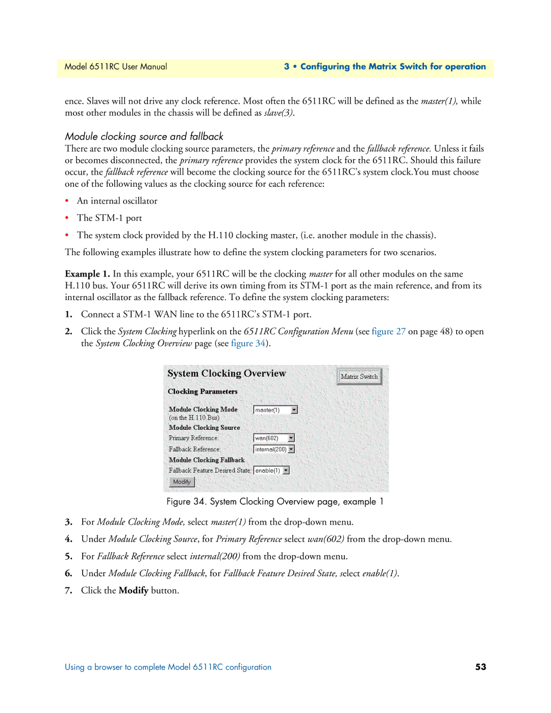
2.Click the System Clocking hyperlink on the 6511RC Configuration Menu (see figure 27 on page 48) to open the System Clocking Overview page (see figure 34).
Figure 34. System Clocking Overview page, example 1
3.For Module Clocking Mode, select master(1) from the
4.Under Module Clocking Source, for Primary Reference select wan(602) from the
5.For Fallback Reference select internal(200) from the
6.Under Module Clocking Fallback, for Fallback Feature Desired State, select enable(1).
7.Click the Modify button.
Using a browser to complete Model 6511RC configuration | 53 |