Model 6511RC User Manual | 3 • Configuring the Matrix Switch for operation |
|
|
Example 2
Map E1 Port 2 received, timeslots
Map E1 Port 2 transmitted, timeslots
Solution:
1.Under E1 Number, select port2(2) from the
2.Under E1 Slots, enter
3.For toH110(5), under H.110 Number, select port1(1) from the
4.For toH110(5), under H.110 slots, enter
5.For fromH110(5), under H.110 Number, select port1(1) from the
6.For fromH110(5), under H.110 slots, enter
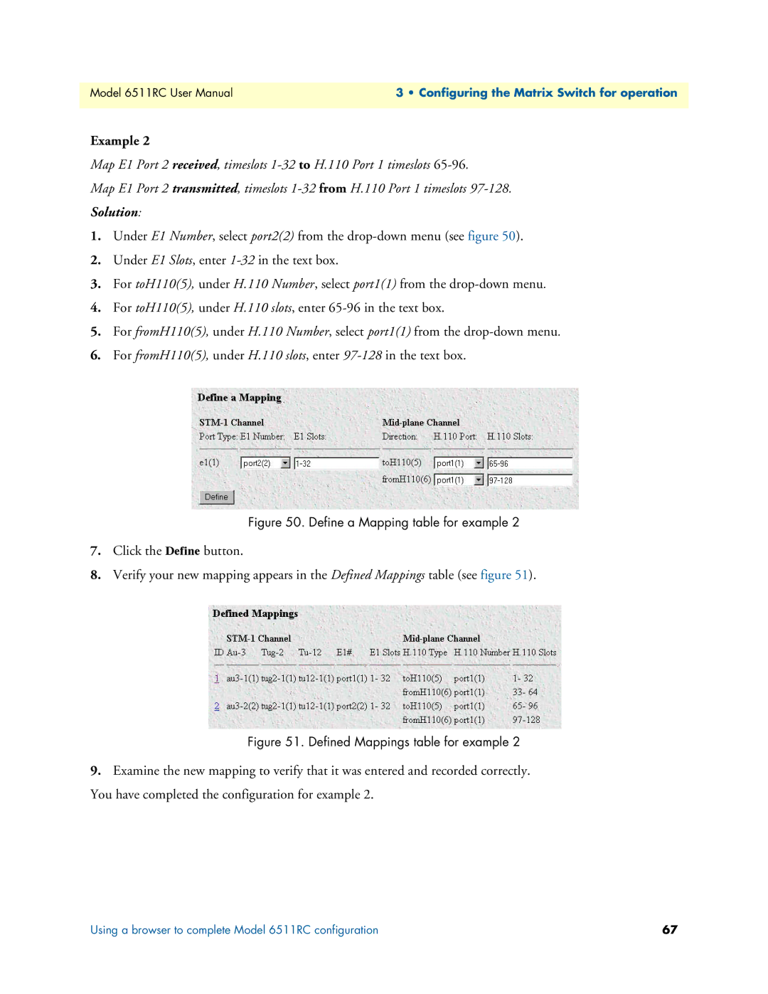
Figure 50. Define a Mapping table for example 2
7.Click the Define button.
8.Verify your new mapping appears in the Defined Mappings table (see figure 51).
Figure 51. Defined Mappings table for example 2
9.Examine the new mapping to verify that it was entered and recorded correctly. You have completed the configuration for example 2.
Using a browser to complete Model 6511RC configuration | 67 |