Patton electronic 6511RC user manual Following sections describe how to define DS0 mappings

Models: 6511RC

1 104
Download 104 pages 44.16 Kb
Page 63
Image 63

Model 6511RC User Manual

3 • Configuring the Matrix Switch for operation


The Matrix Switch offers two formats for defining DS0 mappings:

E1 port format—You will identify the 63 E1 signal streams within the STM-1 link using E1 port numbers 1-63. Those with little to moderate experience working with SDH network architecture will most likely find E1 format to be the simplest and most straightforward method for defining DS0 mappings. Refer to section “Defining DS0 mappings using E1 port format” on page 64.

TU format—You will identify an E1 signal stream according to its location within the STM-1 hierarchy, using the TU-12 number and TUG-2 number within an AUG-3 or within a TUG-3/AUG-4. Experienced SDH engineers with a clear understanding of STM-1 architecture will most likely prefer to use TU format to define DS0 mappings. Refer to section “Defining DS0 mappings using TU format” on page 69.

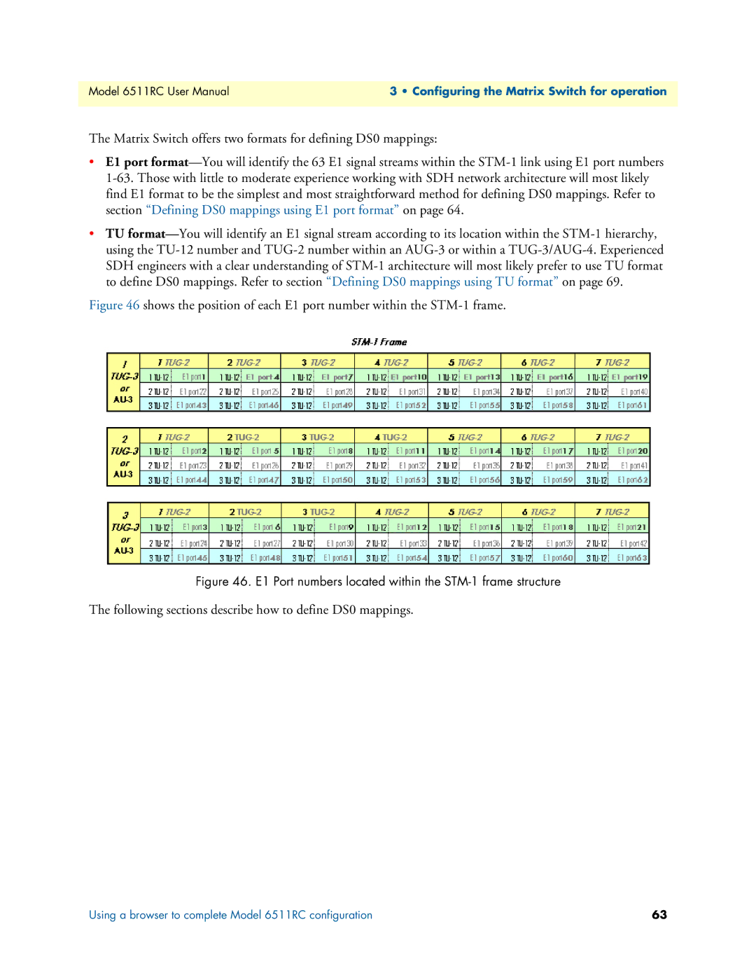
Figure 46 shows the position of each E1 port number within the STM-1 frame.

Figure 46. E1 Port numbers located within the STM-1 frame structure

The following sections describe how to define DS0 mappings.

Using a browser to complete Model 6511RC configuration

63

Page 63
Image 63
Patton electronic 6511RC user manual Following sections describe how to define DS0 mappings