1 • Introduction | Model 6511RC User Manual |
|
|
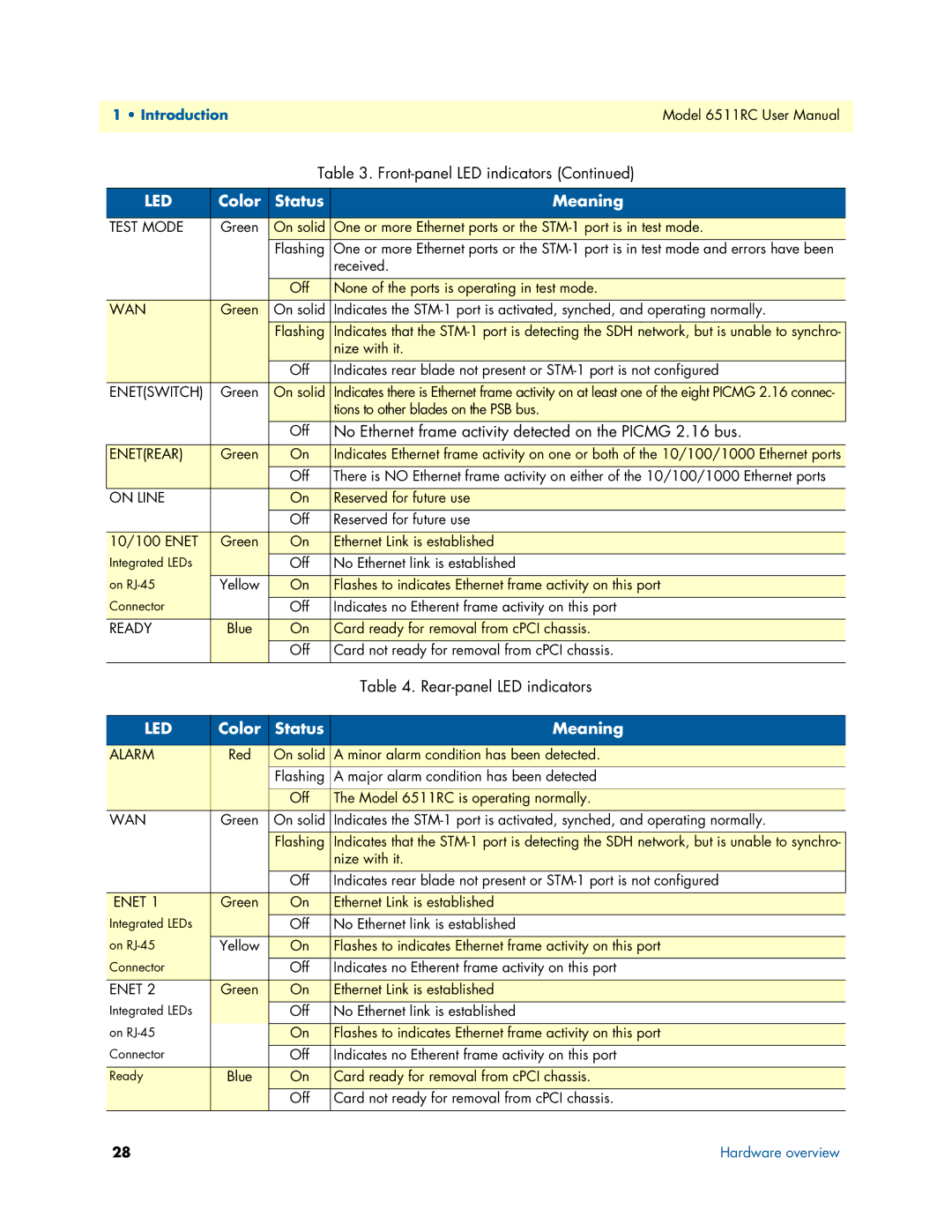
Table 3.
LED | Color | Status | Meaning |
|
|
|
|
TEST MODE | Green | On solid | One or more Ethernet ports or the |
|
| Flashing | One or more Ethernet ports or the |
|
|
| received. |
|
|
|
|
|
| Off | None of the ports is operating in test mode. |
WAN | Green | On solid | Indicates the |
|
|
|
|
|
| Flashing | Indicates that the |
|
|
| nize with it. |
|
| Off | Indicates rear blade not present or |
ENET(SWITCH) | Green | On solid | Indicates there is Ethernet frame activity on at least one of the eight PICMG 2.16 connec- |
|
|
| tions to other blades on the PSB bus. |
|
| Off | No Ethernet frame activity detected on the PICMG 2.16 bus. |
|
|
|
|
ENET(REAR) | Green | On | Indicates Ethernet frame activity on one or both of the 10/100/1000 Ethernet ports |
|
| Off | There is NO Ethernet frame activity on either of the 10/100/1000 Ethernet ports |
ON LINE |
| On | Reserved for future use |
|
| Off | Reserved for future use |
|
|
|
|
10/100 ENET | Green | On | Ethernet Link is established |
Integrated LEDs |
| Off | No Ethernet link is established |
on | Yellow | On | Flashes to indicates Ethernet frame activity on this port |
Connector |
| Off | Indicates no Etherent frame activity on this port |
READY | Blue | On | Card ready for removal from cPCI chassis. |
|
| Off | Card not ready for removal from cPCI chassis. |
|
|
| Table 4. |
LED | Color | Status | Meaning |
|
|
|
|
ALARM | Red | On solid | A minor alarm condition has been detected. |
|
| Flashing | A major alarm condition has been detected |
|
|
|
|
|
| Off | The Model 6511RC is operating normally. |
WAN | Green | On solid | Indicates the |
|
|
|
|
|
| Flashing | Indicates that the |
|
|
| nize with it. |
|
| Off | Indicates rear blade not present or |
|
|
|
|
ENET 1 | Green | On | Ethernet Link is established |
Integrated LEDs |
| Off | No Ethernet link is established |
on | Yellow | On | Flashes to indicates Ethernet frame activity on this port |
Connector |
| Off | Indicates no Etherent frame activity on this port |
ENET 2 | Green | On | Ethernet Link is established |
Integrated LEDs |
| Off | No Ethernet link is established |
|
|
|
|
on |
| On | Flashes to indicates Ethernet frame activity on this port |
Connector |
| Off | Indicates no Etherent frame activity on this port |
|
|
|
|
Ready | Blue | On | Card ready for removal from cPCI chassis. |
|
| Off | Card not ready for removal from cPCI chassis. |
|
|
|
|
28 | Hardware overview |