Model 6511RC User Manual | 3 • Configuring the Matrix Switch for operation |
|
|
ter applies. When the section trace message length is defined to be one byte, the Matrix Switch will ignore the value of Section Trace.
5.For Section Trace Msg Len, from the
6.For Section Trace J0 Byte enter the value your connected SDH network uses for the J0 byte in the SDH frame.
Note J0 applies only with
7.For SDH Payload Mapping, select the payload type corresponding to the way your connected SDH net- work maps the E1 payload into the SDH frame structure. Asynchronous E1 payload mapping is most common, so the factory default value on the Matrix Switch is stm1MappedAsynchE1(0). If your connected SDH network performs
8.For Tx Payload Scramble, if your SDH network expects to receive a scrambled payload select SDHScram- bleEnable(1) from the
9.For Rx Payload Scramble, if your SDH network transmits a scrambled payload select SDHScrambleEn- able(1) from the
10.For SDH Mapping, select the type of AU corresponding to the SDH multiplexing path you desire. To multiplex seven
11.Click the Modify button to save your work into operating memory (volatile DRAM) and activate the new parameter values.
Configuring the SDH path trace parameters
If you selected
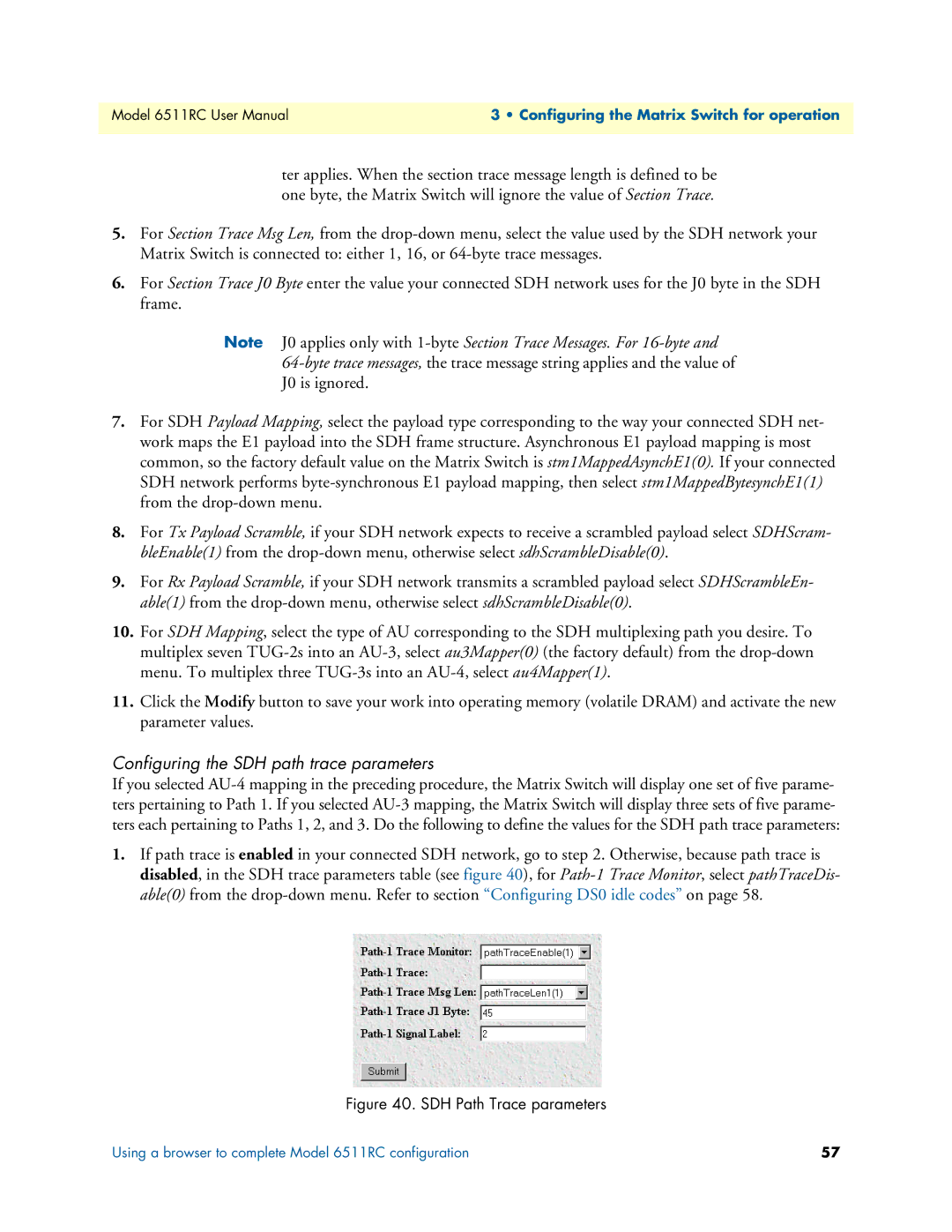
1.If path trace is enabled in your connected SDH network, go to step 2. Otherwise, because path trace is disabled, in the SDH trace parameters table (see figure 40), for
Figure 40. SDH Path Trace parameters
Using a browser to complete Model 6511RC configuration | 57 |