Connecting Alarms
The camera provides an alarm input for external signaling devices, such as door contacts or motion detectors. Both normally open and normally closed devices are supported.
Supervised Alarms
When an alarm is configured as a supervised alarm, the camera maintains a constant electrical current through the alarm circuit
(3.3 VDC, 1 ohm). If the alarm circuit length changes, due to an electrical short or a bypass, the voltage fluctuates from its normal state and activates an alarm.
NOTE: Install the
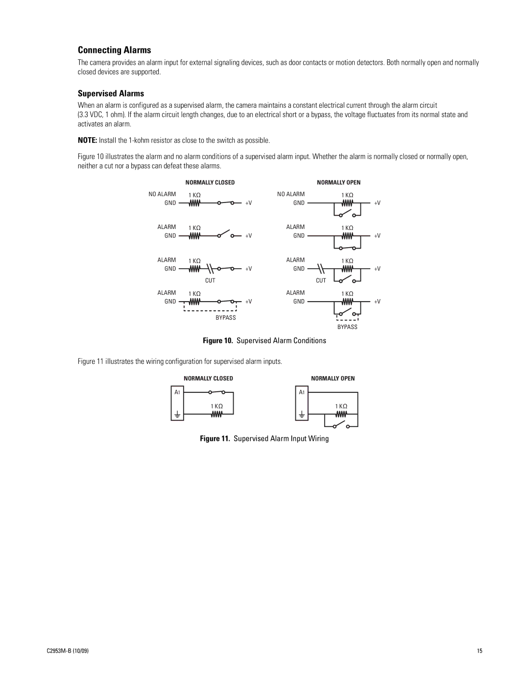
Figure 10 illustrates the alarm and no alarm conditions of a supervised alarm input. Whether the alarm is normally closed or normally open, neither a cut nor a bypass can defeat these alarms.
| NORMALLY CLOSED |
|
| NORMALLY OPEN |
NO ALARM | 1 KΩ |
| NO ALARM | 1 KΩ |
GND |
| +V | GND |
|
ALARM | 1 KΩ |
| ALARM | 1 KΩ |
GND |
| +V | GND |
|
ALARM | 1 KΩ |
| ALARM | 1 KΩ |
GND |
| +V | GND |
|
| CUT |
|
| CUT |
ALARM | 1 KΩ |
| ALARM | 1 KΩ |
GND |
| +V | GND |
|
| BYPASS |
|
|
|
|
|
|
| BYPASS |
Figure 10. Supervised Alarm Conditions
Figure 11 illustrates the wiring configuration for supervised alarm inputs.
|
|
|
|
|
| NORMALLY CLOSED |
|
|
|
|
|
| NORMALLY OPEN | |||
|
|
|
|
|
|
|
|
|
|
|
|
|
|
|
|
|
A1 |
| A1 |
| |||||||||||||
|
|
|
|
|
| 1 KΩ |
|
|
|
|
|
|
|
| 1 KΩ | |
|
|
|
|
|
|
|
|
|
|
|
|
|
|
|
|
|
|
|
|
|
|
|
|
|
|
|
|
|
|
|
|
|
|
|
|
|
|
|
|
|
|
|
|
|
|
|
|
|
|
|
|
|
|
|
|
|
|
|
|
|
|
|
|
|
|
|
|
+V
+V
+V
+V
Figure 11. Supervised Alarm Input Wiring
| 15 |