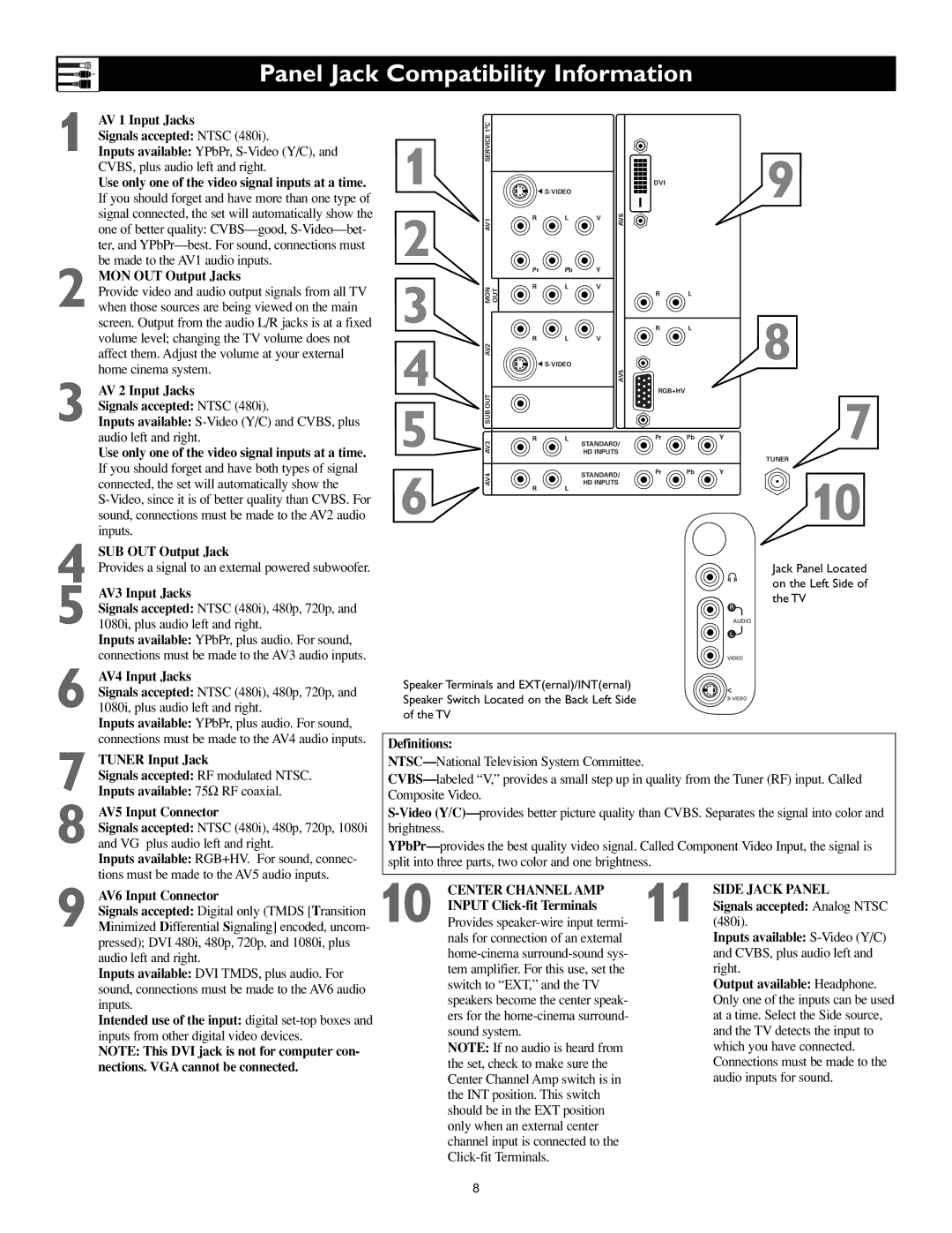
Panel Jack Compatibility Information
1 AV 1 Input Jacks
Signals accepted: NTSC (480i).
Inputs available: YPbPr,
Use only one of the video signal inputs at a time.
If you should forget and have more than one type of signal connected, the set will automatically show the one of better quality:
2 MON OUT Output Jacks
Provide video and audio output signals from all TV when those sources are being viewed on the main screen. Output from the audio L/R jacks is at a fixed volume level; changing the TV volume does not affect them. Adjust the volume at your external home cinema system.
3 AV 2 Input Jacks
Signals accepted: NTSC (480i).
Inputs available:
Use only one of the video signal inputs at a time.
If you should forget and have both types of signal connected, the set will automatically show the
4 SUB OUT Output Jack
Provides a signal to an external powered subwoofer.
5 AV3 Input Jacks
Signals accepted: NTSC (480i), 480p, 720p, and 1080i, plus audio left and right.
Inputs available: YPbPr, plus audio. For sound, connections must be made to the AV3 audio inputs.
6 AV4 Input Jacks
Signals accepted: NTSC (480i), 480p, 720p, and 1080i, plus audio left and right.
Inputs available: YPbPr, plus audio. For sound, connections must be made to the AV4 audio inputs.
7 TUNER Input Jack
Signals accepted: RF modulated NTSC.
Inputs available: 75Ω RF coaxial.
8 AV5 Input Connector
Signals accepted: NTSC (480i), 480p, 720p, 1080i and VG plus audio left and right.
Inputs available: RGB+HV. For sound, connec- tions must be made to the AV5 audio inputs.
9 AV6 Input Connector
Signals accepted: Digital only (TMDS [Transition Minimized Differential Signaling] encoded, uncom- pressed); DVI 480i, 480p, 720p, and 1080i, plus audio left and right.
Inputs available: DVI TMDS, plus audio. For sound, connections must be made to the AV6 audio inputs.
Intended use of the input: digital
NOTE: This DVI jack is not for computer con- nections. VGA cannot be connected.
| C |
|
|
|
|
|
|
|
|
|
| 2 |
|
|
|
|
|
|
|
|
|
1 | SERVICE 1 |
|
|
|
|
|
|
|
| 9 |
|
| G |
|
| DVI |
|
| |||
2 | AV1 | R |
| L | V | AV6 |
|
|
|
|
| Pr | Pb | Y |
|
|
|
|
| ||
|
|
|
|
|
|
| ||||
3 | MON OUT | R |
| L | V |
|
|
|
|
|
|
|
|
|
| R | L |
|
| ||
|
|
|
|
|
|
| R | L |
|
|
4 | AV2 | R |
| L | V |
|
|
|
| 8 |
|
|
|
|
|
|
|
| |||
|
| G |
| AV5 |
|
|
| |||
|
|
|
|
|
|
|
|
| ||
AV3 SUB OUT |
|
|
|
|
| RGB+HV |
|
| 7 | |
5 | R |
| L | HD INPUTS | Pr | Pb | Y | |||
|
|
| STANDARD/ |
|
|
| ||||
|
|
|
|
|
|
|
|
|
| TUNER |
6 | AV4 |
|
|
| STANDARD/ | Pr | Pb | Y | 10 | |
|
|
|
|
|
| |||||
R |
| L | HD INPUTS |
|
|
| ||||
|
|
|
|
|
|
| ||||
|
|
|
|
|
|
|
|
| ||
Jack Panel Located on the Left Side of the TV
Speaker Terminals and EXT(ernal)/INT(ernal) Speaker Switch Located on the Back Left Side of the TV
Definitions:
NTSC—National Television System Committee.
10 | CENTER CHANNEL AMP | 11 | SIDE JACK PANEL |
INPUT | Signals accepted: Analog NTSC | ||
Provides | (480i). | ||
| nals for connection of an external |
| Inputs available: |
|
| and CVBS, plus audio left and | |
| tem amplifier. For this use, set the |
| right. |
| switch to “EXT,” and the TV |
| Output available: Headphone. |
| speakers become the center speak- |
| Only one of the inputs can be used |
| ers for the |
| at a time. Select the Side source, |
| sound system. |
| and the TV detects the input to |
| NOTE: If no audio is heard from |
| which you have connected. |
| the set, check to make sure the |
| Connections must be made to the |
| Center Channel Amp switch is in |
| audio inputs for sound. |
| the INT position. This switch |
|
|
| should be in the EXT position |
|
|
| only when an external center |
|
|
channel input is connected to the
8