Connecting an HD Satellite Receiver to YPbPr
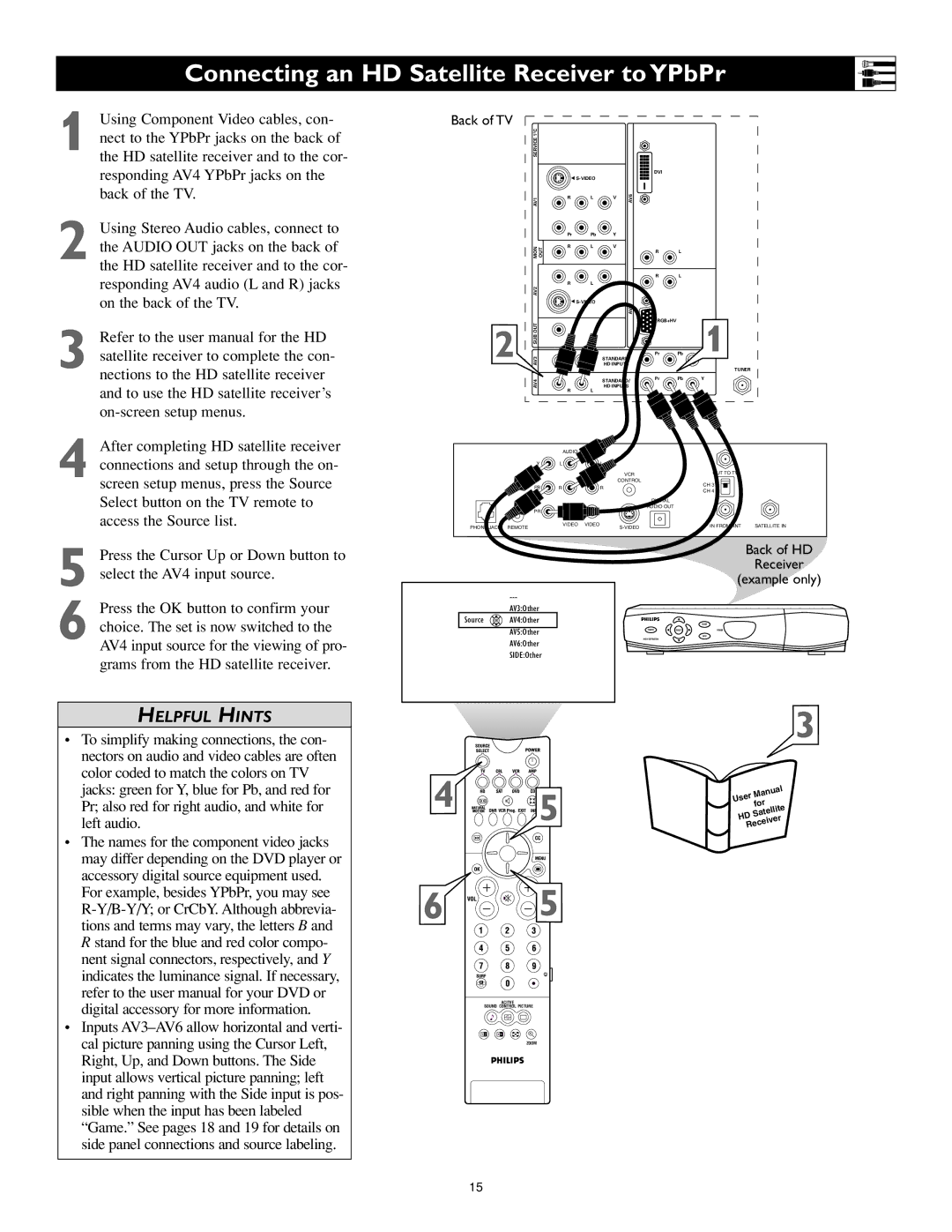
1 Using Component Video cables, con- nect to the YPbPr jacks on the back of the HD satellite receiver and to the cor- responding AV4 YPbPr jacks on the back of the TV.
2 Using Stereo Audio cables, connect to the AUDIO OUT jacks on the back of the HD satellite receiver and to the cor- responding AV4 audio (L and R) jacks on the back of the TV.
3 Refer to the user manual for the HD satellite receiver to complete the con- nections to the HD satellite receiver and to use the HD satellite receiver’s
4 After completing HD satellite receiver connections and setup through the on- screen setup menus, press the Source Select button on the TV remote to access the Source list.
Back of TV | C |
|
|
|
|
|
|
|
|
| 2 |
|
|
|
|
|
|
|
|
| SERVICE 1 |
|
|
|
|
|
|
|
|
|
|
|
|
|
|
| DVI |
|
|
|
|
| G |
|
|
|
|
| |
| AV1 |
| R | L | V | AV6 |
|
|
|
|
|
| Pr | Pb | Y |
|
|
|
|
| MON | OUT | R | L | V |
| R | L |
|
|
|
|
|
|
| ||||
|
|
|
|
|
|
| R | L |
|
| AV2 |
| R | L | V |
|
|
|
|
|
|
|
|
|
|
|
|
| |
|
|
| G |
| AV5 |
|
|
| |
|
|
|
|
|
|
|
|
| |
2 | SUB OUT |
|
|
|
|
| RGB+HV |
| 1 |
|
|
|
|
|
|
| |||
AV3 |
|
|
| STANDARD/ | Pr | Pb | |||
|
|
| HD INPUTS |
|
| TUNER | |||
|
|
|
|
|
|
|
|
| |
| AV4 |
|
|
| STANDARD/ | Pr | Pb | Y | |
|
|
|
|
|
|
| |||
|
| R | L | HD INPUTS |
|
|
| ||
|
|
|
|
|
|
|
| ||
|
|
| AUDIO |
|
|
|
|
|
|
| Y | L |
|
|
|
|
|
| |
|
|
|
|
|
| VCR |
|
| OUT TO TV |
|
|
|
|
|
| CONTROL |
|
|
|
PB | R | R |
| CH 3 |
|
| CH 4 |
| |||
|
|
|
|
| |
|
|
|
| DIGITAL |
|
PR |
|
|
| AUDIO OUT |
|
|
|
|
|
| |
PHONE JACK REMOTE | VIDEO VIDEO |
| IN FROM ANT | SATELLITE IN |
5 Press the Cursor Up or Down button to select the AV4 input source.
6 Press the OK button to confirm your choice. The set is now switched to the AV4 input source for the viewing of pro- grams from the HD satellite receiver.
AV3:Other
Source ![]() OK
OK![]() AV4:Other
AV4:Other
AV5:Other
AV6:Other
SIDE:Other
Back of HD
Receiver
(example only)
GUIDE
POWER | SELECT | POWER |
INFO
HIGH DEFINITION
HELPFUL HINTS
•To simplify making connections, the con- nectors on audio and video cables are often color coded to match the colors on TV jacks: green for Y, blue for Pb, and red for Pr; also red for right audio, and white for left audio.
•The names for the component video jacks may differ depending on the DVD player or accessory digital source equipment used. For example, besides YPbPr, you may see
•Inputs
4![]()
 5
5
6 ![]()
![]()
![]()
![]()
![]() 5
5
ACITVE
SOUND CONTROL PICTURE
1 2
ZOOM
3
User | Manual | |
for | ||
| ||
HD | Satellite | |
| ||
Receiver | ||
15