Installation
English
Connections - back of your DVD Recorder
-Please refer to your TV, VCR, Stereo and any other User Manual(s) as necessary to make the optimal connections.
-Do not connect the power cards until all other connections are made.
-Do not connect your DVD Recorder to your TV via your VCR. The video quality could be distorted by the copy protection system.
-For better sound, connect the Recorder’s audio outputs to your amplifier, receiver, stereo system or A/V equipment. See ‘Connecting to an A/V receiver or A/V amplifier.’
Caution:
Do not connect the Recorder’s audio output to the phone input of your audio system. This could damage your equipment.
Step 1: Connecting to the antenna or Cable TV signal
•Remove the antenna cable from your TV and connect it to the ANTENNA jack at the back of the DVD Recorder.
•Connect one end of the antenna cable supplied (1) to the TV jack on the DVD Recorder and the other end to the antenna input jack on your TV.
The antenna connection transmits TV channels through the Recorder to the TV, you still need a video connection to sent DVD playback from the Recorder to the TV. See ‘Connecting to a TV.’
Step 2: Connecting to a TV
To obtain the highest possible picture and sound quality from your TV, use the Progressive Scan video jacks on the DVD Recorder and TV.
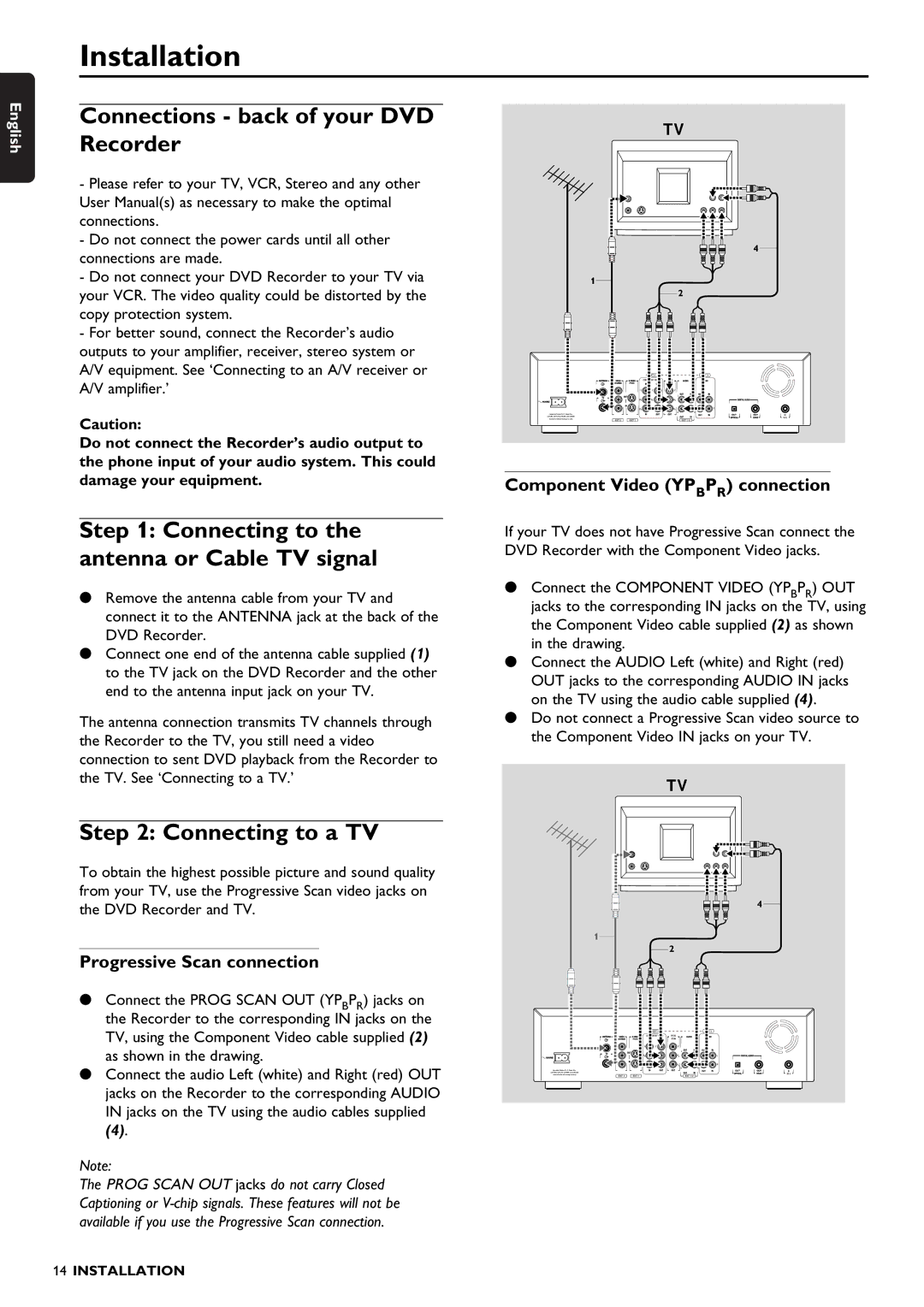
Progressive Scan connection
•Connect the PROG SCAN OUT (YPBPR) jacks on the Recorder to the corresponding IN jacks on the TV, using the Component Video cable supplied (2) as shown in the drawing.
•Connect the audio Left (white) and Right (red) OUT jacks on the Recorder to the corresponding AUDIO IN jacks on the TV using the audio cables supplied
(4).
Note:
The PROG SCAN OUT jacks do not carry Closed Captioning or
TV
4
1
2
| EXT 3 |
| EXT 3 |
| COMPONENT VIDEO | PROG |
|
|
| SCAN |
|
Y | Y | Y |
|
|
| L | L |
PB | PB | PB | L |
PR | PR | PR | R |
|
| R | R |
Apparatus Claims of U. S. Patent Nos. |
|
|
| IN |
4,631,603, 4,577,216, 4,819,098, and 4,907,093 |
|
|
| |
licensed for limited viewing uses only. | EXT 2 | EXT 1 |
| RC 6 |
| EXT 1/2 | |||
|
|
|
|
|
|
|
|
|
|
Component Video (YPBPR) connection
If your TV does not have Progressive Scan connect the DVD Recorder with the Component Video jacks.
•Connect the COMPONENT VIDEO (YPBPR) OUT jacks to the corresponding IN jacks on the TV, using the Component Video cable supplied (2) as shown in the drawing.
•Connect the AUDIO Left (white) and Right (red) OUT jacks to the corresponding AUDIO IN jacks on the TV using the audio cable supplied (4).
•Do not connect a Progressive Scan video source to the Component Video IN jacks on your TV.
TV
4
1
|
| 2 |
|
| EXT 3 |
| EXT 3 |
| COMPONENT VIDEO | PROG |
|
|
| SCAN |
|
Y | Y | Y |
|
|
| L | L |
PB | PB | PB | L |
PR | PR | PR | R |
|
| R | R |
Apparatus Claims of U. S. Patent Nos. |
|
|
| IN |
4,631,603, 4,577,216, 4,819,098, and 4,907,093 |
|
|
| |
licensed for limited viewing uses only. | EXT 2 | EXT 1 |
| RC 6 |
| EXT 1/2 | |||
|
|
|
|
|
|
|
|
|
|
14INSTALLATION