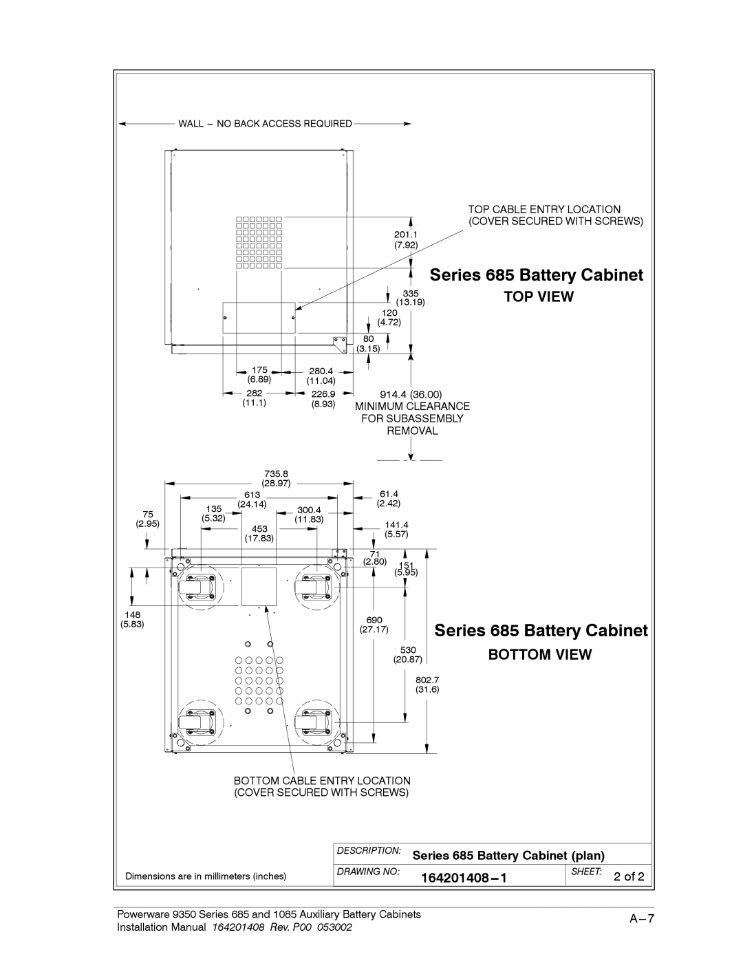
WALL
TOP CABLE ENTRY LOCATION (COVER SECURED WITH SCREWS)
201.1
(7.92)
Series 685 Battery Cabinet
|
|
|
|
| 335 | |
|
|
|
|
| (13.19) | |
|
|
|
| 120 | ||
|
|
|
| (4.72) | ||
|
|
|
| 80 |
| |
|
|
|
| (3.15) |
| |
|
| 175 | 280.4 |
|
| |
|
| (6.89) | (11.04) |
|
| |
|
| 282 | 226.9 | 914.4 (36.00) | ||
|
| (11.1) | (8.93) | MINIMUM CLEARANCE | ||
|
|
|
| FOR SUBASSEMBLY | ||
|
|
|
| REMOVAL | ||
|
| 735.8 |
|
|
| |
|
| (28.97) |
| 61.4 | ||
|
| 613 |
| |||
75 | 135 | (24.14) | 300.4 | (2.42) | ||
|
|
| ||||
(5.32) |
| (11.83) |
|
| ||
(2.95) | 453 | 141.4 | ||||
|
| |||||
|
|
| (5.57) | |||
|
| (17.83) |
| |||
|
|
|
|
| ||
|
|
|
| 71 |
| |
|
|
|
| (2.80) | 151 | |
|
|
|
|
| (5.95) | |
TOP VIEW
148 | 690 | |
(5.83) | ||
(27.17) | ||
|
Series 685 Battery Cabinet
530
(20.87)
802.7
(31.6)
BOTTOM VIEW
BOTTOM CABLE ENTRY LOCATION (COVER SECURED WITH SCREWS)
Dimensions are in millimeters (inches)
DESCRIPTION: Series 685 Battery Cabinet (plan)
DRAWING NO: | SHEET: 2 of 2 |
Powerware 9350 Series 685 and 1085 Auxiliary Battery Cabinets | |
Installation Manual 164201408 Rev. P00 053002 |
|