E T A E
TTT
AA
AA
EE
TTT
E A T E
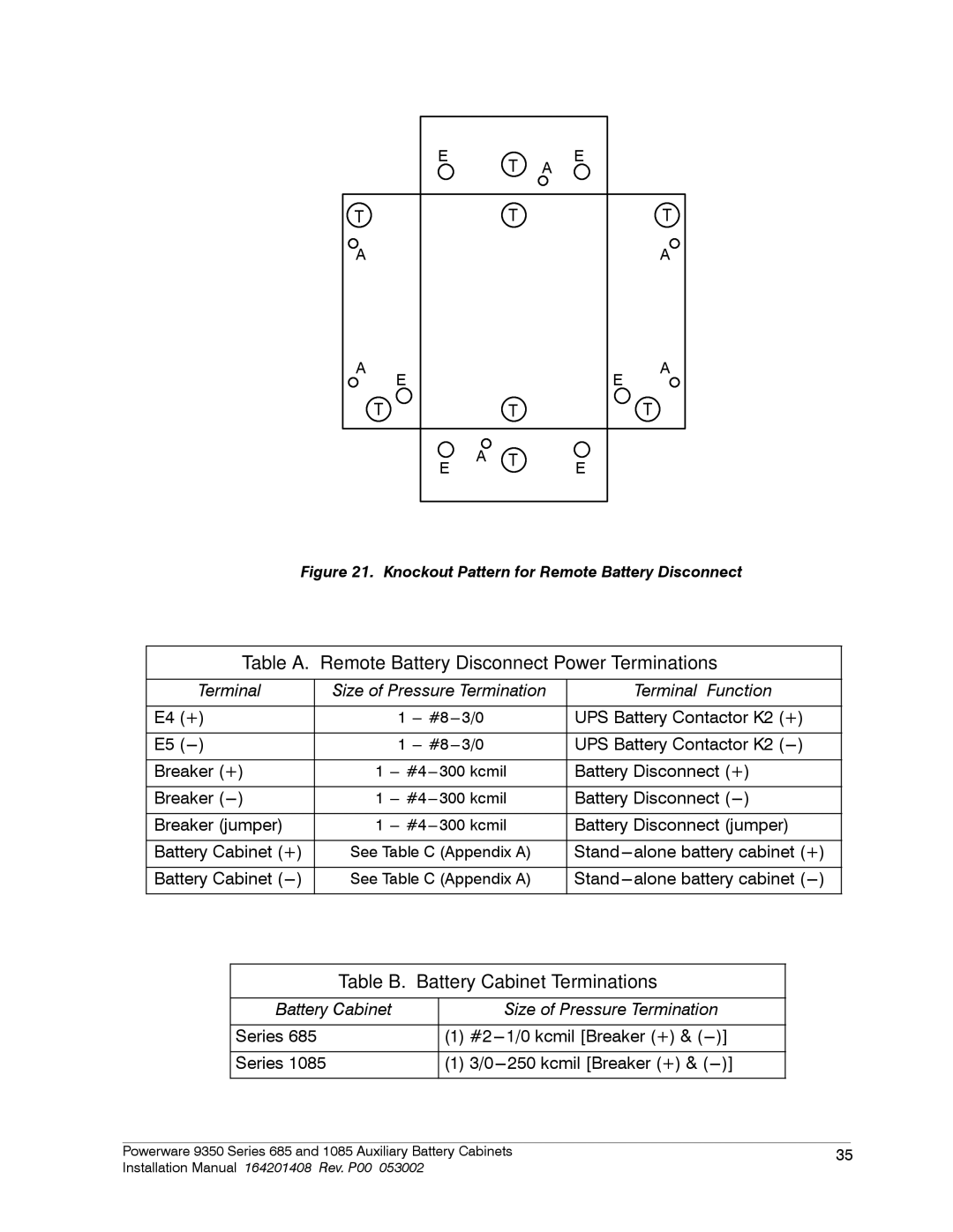
Figure 21. Knockout Pattern for Remote Battery Disconnect
Table A. Remote Battery Disconnect Power Terminations
| Terminal | Size of Pressure Termination |
| Terminal Function | |||
|
|
|
|
|
|
| |
E4 | (+) |
| 1 | 3/0 | UPS Battery Contactor K2 (+) | ||
|
|
|
|
|
|
| |
E5 |
| 1 | 3/0 | UPS Battery Contactor K2 ( | |||
|
|
|
|
| |||
Breaker (+) | 1 | Battery Disconnect (+) | |||||
|
|
|
|
| |||
Breaker ( | 1 | Battery Disconnect ( | |||||
|
|
|
|
| |||
Breaker (jumper) | 1 | Battery Disconnect (jumper) | |||||
|
|
|
| ||||
Battery Cabinet (+) | See Table C (Appendix A) | alone battery cabinet (+) | |||||
|
|
|
| ||||
Battery Cabinet ( | See Table C (Appendix A) | alone battery cabinet | |||||
|
|
|
|
|
|
|
|
Table B. Battery Cabinet Terminations
Battery Cabinet |
|
| Size of Pressure Termination | |
Series 685 | (1) | 1/0 kcmil [Breaker (+) & | )] | |
Series 1085 | (1) | 250 kcmil [Breaker (+) & | )] | |
|
|
|
Powerware 9350 Series 685 and 1085 Auxiliary Battery Cabinets | 35 | |
Installation Manual 164201408 Rev. P00 053002 |
|
|