1 |
| 2 | 3 |
| 4 | 5 |
| 6 | 7 |
| 8 | 9 10 11 12 | |||||||||||
|
|
|
|
|
|
|
|
|
|
|
|
|
|
|
|
|
|
|
|
|
|
|
|
|
|
|
|
|
|
|
|
|
|
|
|
|
|
|
|
|
|
|
|
|
|
|
|
|
|
|
|
|
|
|
|
|
|
|
|
|
|
|
|
|
|
|
|
|
|
|
|
|
|
|
|
|
|
|
|
|
|
|
|
|
|
|
|
|
|
|
|
|
|
|
|
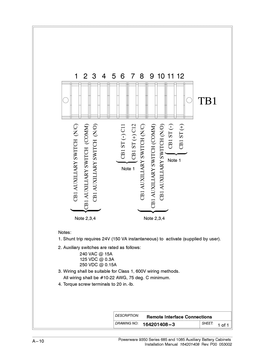
TB1
CB1 AUXILIARY SWITCH (N/C) | CB1 AUXILIARY SWITCH (COMM) CB1 AUXILIARY SWITCH (N/O) |
Note 2,3,4
(+) C12 | |
CB1 ST | CB1 ST |
Note 1
SWITCHAUXILIARYCB1 (N/C) | SWITCHAUXILIARYCB1(COMM) | SWITCHAUXILIARYCB1 (N/O) | (+) | |
CB1 ST | CB1 ST |
Note 1
Note 2,3,4
Notes:
1.Shunt trip requires 24V (150 VA instantaneous) to activate (supplied by user).
2.Auxiliary switches are rated as follows:
240 VAC @ 15A
125 VDC @ 0.3A
250 VDC @ 0.15A
3.Wiring shall be suitable for Class 1, 600V wiring methods. All wiring shall be
4.Torque screw terminals to 20
| DESCRIPTION: | Remote Interface Connections |
|
| ||
|
|
|
|
|
|
|
| DRAWING NO: |
|
| SHEET: | 1 of 1 |
|
|
|
|
| |||
|
|
|
|
|
|
|
|
|
|
|
|
|
|
Powerware 9350 Series 685 and 1085 Auxiliary Battery Cabinets | ||||||
|
| Installation Manual | 164201408 Rev. P00 | 053002 | ||