.SP6498 Belt Drive Saw 05/03 7/15/03 7:04 AM Page 18
Assembly (continued)
Installing Elevation Handwheel
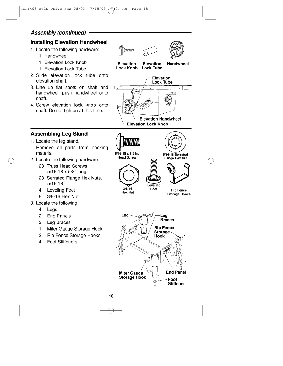
1.Locate the following hardware:
1Handwheel
1Elevation Lock Knob
1Elevation Lock Tube
2.Slide elevation lock tube onto elevation shaft.
3.Line up flat spots on shaft and handwheel, push handwheel onto shaft.
4.Screw elevation lock knob onto shaft. Do not tighten at this time.
Elevation Elevation Handwheel Lock Knob Lock Tube
Elevation
Lock Tube
![]() Elevation Handwheel
Elevation Handwheel
Elevation Lock Knob
Assembling Leg Stand
1.Locate the leg stand.
Remove all parts from packing material.
2.Locate the following hardware:
23Truss Head Screws,
23Serrated Flange Hex Nuts,
4Leveling Feet
8
3.Locate the following:
4Legs
2End Panels
2Leg Braces
1Miter Gauge Storage Hook
2Rip Fence Storage Hooks
4Foot Stiffeners
|
|
|
|
| |
|
| |
| ||
Head Screw |
| |
| Flange Hex Nut | |
|
|
|
|
| Leveling |
|
| Foot | Rip Fence | |
Hex Nut |
| ||
| |||
| Storage Hooks | ||
|
|
| |
Leg | Leg |
| Braces |
Rip Fence
Storage
Hook
Miter Gauge | End Panel |
Storage Hook | Foot |
| |
| Stiffener |
18
