.SP6498 Belt Drive Saw 05/03 7/15/03 7:04 AM Page 36
Assembly (continued)
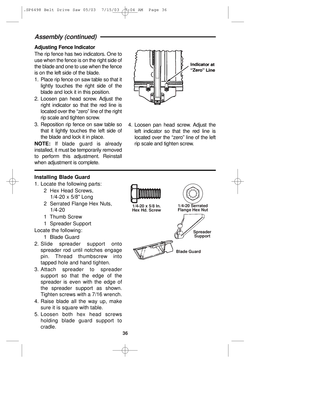
Adjusting Fence Indicator
The rip fence has two indicators. One to use when the fence is on the right side of the blade and one to use when the fence is on the left side of the blade.
1.Place rip fence on saw table so that it lightly touches the right side of the blade and lock it in this position.
2.Loosen pan head screw. Adjust the right indicator so that the red line is located over the “zero” line of the right rip scale and tighten screw.
3. Reposition rip fence on saw table so | 4. Loosen pan head screw. Adjust the |
that it lightly touches the left side of | left indicator so that the red line is |
the blade and lock it in place. | located over the “zero” line of the left |
NOTE: If blade guard is already | rip scale and tighten screw. |
installed, it must be temporarily removed |
|
to perform this adjustment. Reinstall |
|
when adjustment is complete. |
|
Installing Blade Guard
1.Locate the following parts: 2 Hex Head Screws,
2 | Serrated Flange Hex Nuts, | |||
|
| Hex Hd. Screw | Flange Hex Nut | |
1 | Thumb Screw |
|
|
|
1 | Spreader Support |
|
|
|
Locate the following: |
|
| Spreader | |
1 | Blade Guard |
|
| Support |
2. Slide spreader support | onto |
|
| |
spreader rod until notches engage |
| Blade Guard | ||
pin. | Thread thumbscrew | into |
|
|
tapped hole and hand tighten. |
|
|
| |
3.Attach spreader to spreader support so that the edge of the spreader is even with the edge of the spreader support as shown. Tighten screws with a 7/16 wrench.
4.Raise blade all the way up, make sure it is square with table.
5.Loosen both hex head screws holding blade guard support to cradle.
36