.SP6498 Belt Drive Saw 05/03 7/15/03 7:04 AM Page 27
Assembling Herc-U-Lift™ Caster System
Assembly Tips
1.The caster set consists of an upper and lower assembly.
2.First put the upper and lower assembly together following instruc- tions below.
3.Loosely assemble all nut and screw connections. After mounting the assemblies on the table saw, adjust frames on center, and then securely tighten all fasteners.
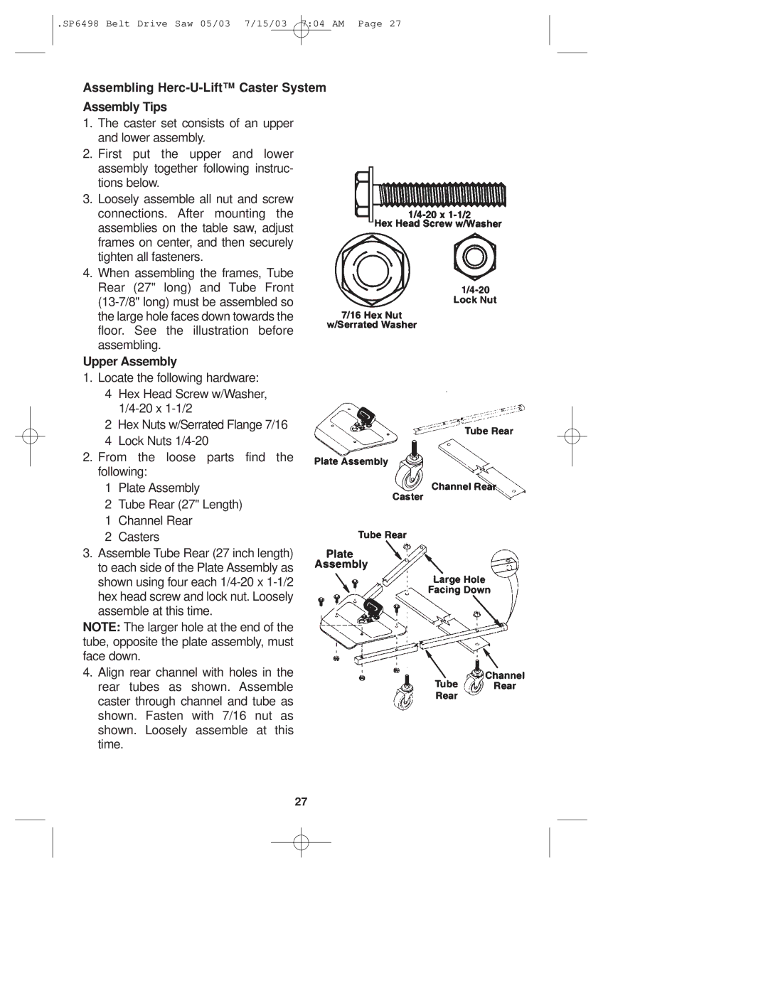
4.When assembling the frames, Tube Rear (27" long) and Tube Front
Upper Assembly
1. Locate the following hardware:
4Hex Head Screw w/Washer,
2Hex Nuts w/Serrated Flange 7/16
4Lock Nuts
2.From the loose parts find the following:
1Plate Assembly
2Tube Rear (27" Length)
1Channel Rear
2Casters
3.Assemble Tube Rear (27 inch length) to each side of the Plate Assembly as shown using four each
NOTE: The larger hole at the end of the tube, opposite the plate assembly, must face down.
4.Align rear channel with holes in the rear tubes as shown. Assemble caster through channel and tube as shown. Fasten with 7/16 nut as shown. Loosely assemble at this time.
27
