.SP6498 Belt Drive Saw 05/03 7/15/03 7:04 AM Page 41
Mounting Switch on Right Side
1.Slide the nuts into the lower slot of the front guide bar from the right end, with the switch facing front.
2.Slide switch assembly left until the left side of switch assembly is in line with right side of main saw table - tighten screws.
Mounting Switch on Left Side
1.Slide the nuts into the lower slot of the front guide bar from the left end, running wire behind unit, with switch facing front.
2.Slide the assembly right until the right side of the switch assembly is in line with the left side of the main saw table - tighten screws.
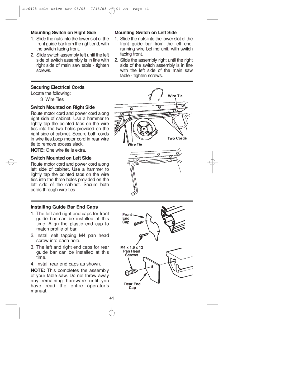
Securing Electrical Cords
Locate the following: 3 Wire Ties
Switch Mounted on Right Side
Route motor cord and power cord along right side of cabinet. Use a hammer to lightly tap the pointed tabs on the wire ties into the two holes provided on the right side of cabinet. Secure both cords in wire ties.Loop motor cord in rear wire tie to remove excess slack.
NOTE: One wire tie is extra.
Switch Mounted on Left Side
Route motor cord and power cord along left side of cabinet. Use a hammer to lightly tap the pointed tabs on the wire ties into the three holes provided on the left side of the cabinet. Secure both cords through wire ties.
Installing Guide Bar End Caps
1.The left and right end caps for front guide bar can be installed at this time. Align the plastic end cap to match profile of bar.
2.Install self tapping M4 pan head screw into each hole.
3.The left and right end caps for rear guide bar can be installed at this time.
4.Install rear end caps as shown.
NOTE: This completes the assembly of your table saw. Do not throw away any remaining hardware until you have read the entire operator’s manual.
Front
End
Cap
M4 x 1.6 x 12
Pan Head
Screws
Rear End
Cap
41