.SP6498 Belt Drive Saw 05/03 7/15/03 7:04 AM Page 29
Assembling
Installation Instructions
WARNING: To reduce the risk of injury from unexpected starting, unplug the tool before attaching caster set.
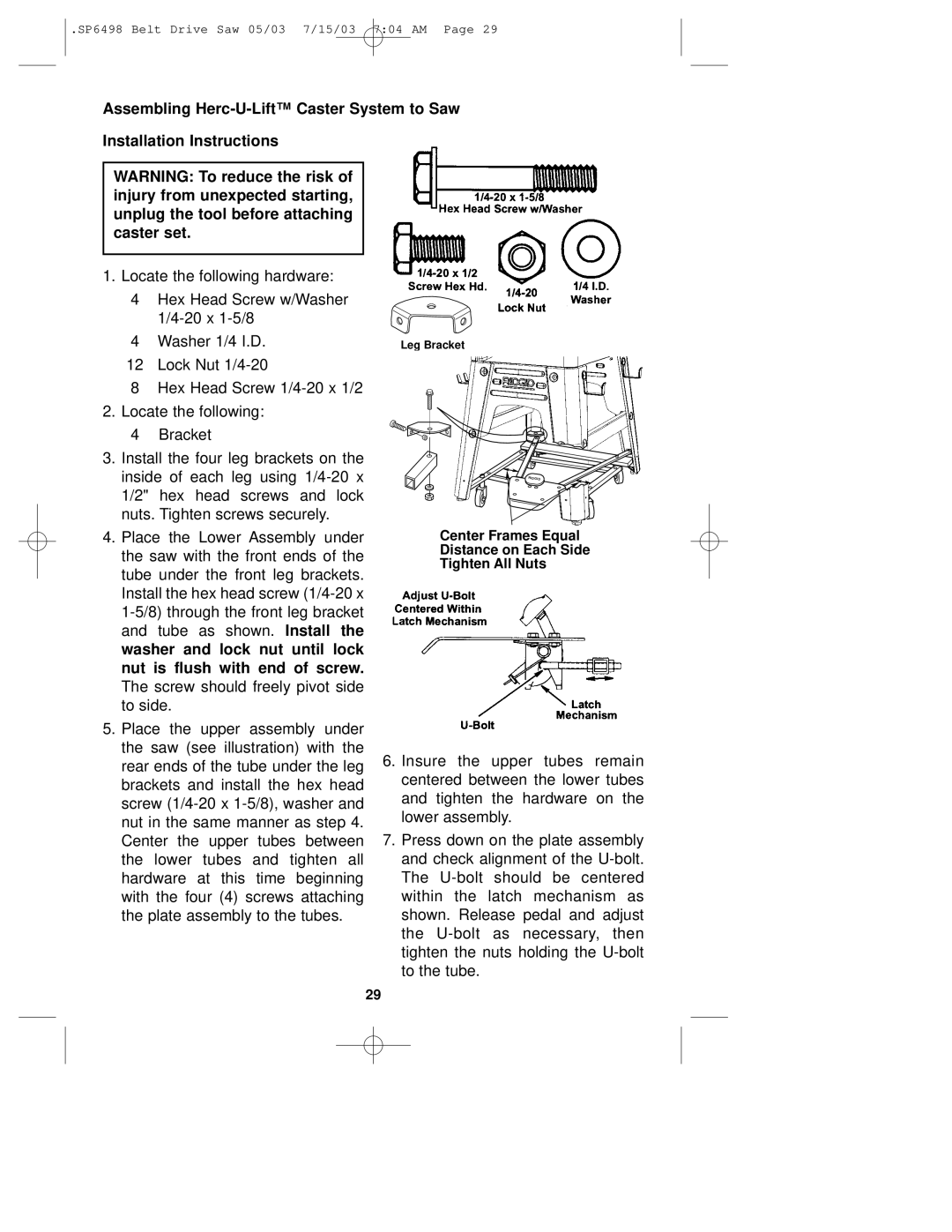
1. Locate the following hardware:
4Hex Head Screw w/Washer
4Washer 1/4 I.D.
12 Lock Nut
8Hex Head Screw
2.Locate the following:
4Bracket
3.Install the four leg brackets on the inside of each leg using
4.Place the Lower Assembly under the saw with the front ends of the tube under the front leg brackets. Install the hex head screw
5.Place the upper assembly under the saw (see illustration) with the rear ends of the tube under the leg brackets and install the hex head screw
Leg Bracket
Center Frames Equal
Distance on Each Side
Tighten All Nuts
6.Insure the upper tubes remain centered between the lower tubes and tighten the hardware on the lower assembly.
7.Press down on the plate assembly and check alignment of the
29