Chapter 3. Hardware Installation
The sensor specifications are as follows.
| No. of inputs | 16 transistor input | |
|
|
| |
Specification | Input types | N.C, N.O support | |
|
| ||
Support Sensor | Dry contact sensor | ||
| |||
|
|
| |
| Connection method | Insert stripped wire end into terminal block | |
|
|
| |
Electric | Pulse width of usable | Minimum 500ms | |
input | |||
capacity |
| ||
|
| ||
Output power | Typical DC 12mA | ||
| |||
|
|
|
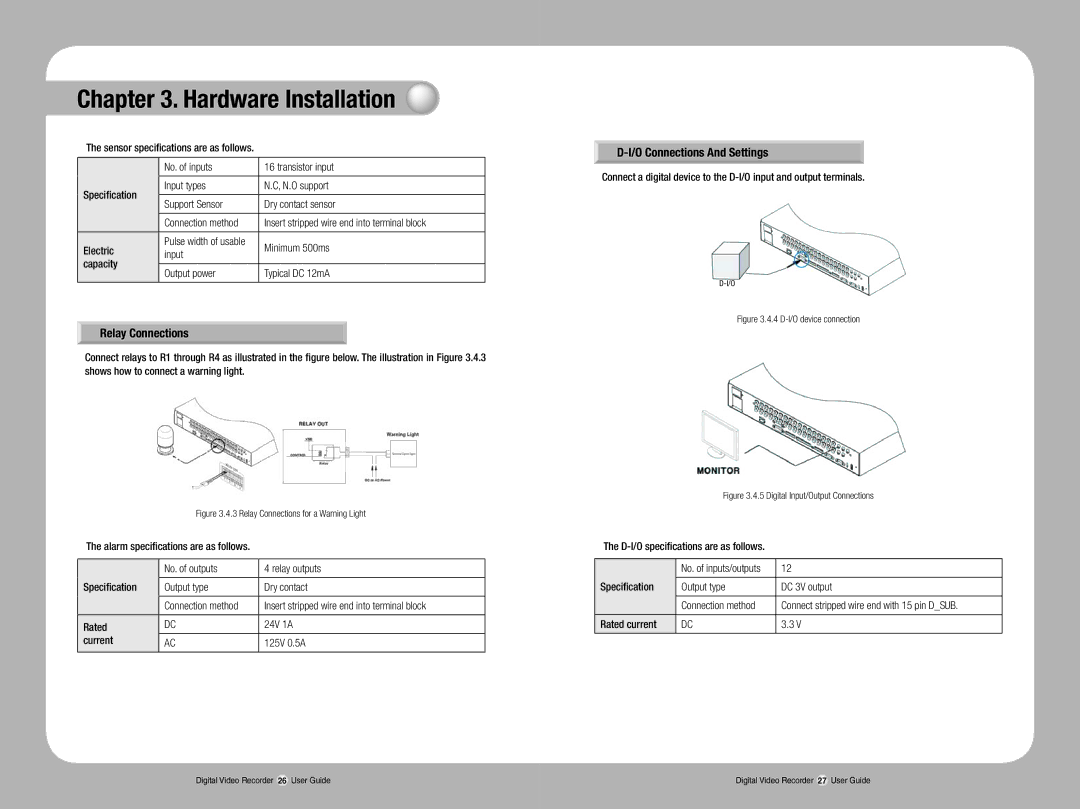
Relay Connections
Connect relays to R1 through R4 as illustrated in the figure below. The illustration in Figure 3.4.3 shows how to connect a warning light.
Figure 3.4.3 Relay Connections for a Warning Light
The alarm specifications are as follows.
| No. of outputs | 4 relay outputs |
Specification |
|
|
Output type | Dry contact | |
|
|
|
| Connection method | Insert stripped wire end into terminal block |
|
|
|
Rated | DC | 24V 1A |
current | AC | 125V 0.5A |
|
|
|
D-I/O Connections And Settings
Connect a digital device to the
Figure 3.4.4 D-I/O device connection
Figure 3.4.5 Digital Input/Output Connections
The
| No. of inputs/outputs | 12 |
Specification |
|
|
Output type | DC 3V output | |
|
|
|
| Connection method | Connect stripped wire end with 15 pin D_SUB. |
|
|
|
Rated current | DC | 3.3 V |
|
|
|
Digital Video Recorder 26 User Guide | Digital Video Recorder 27 User Guide |