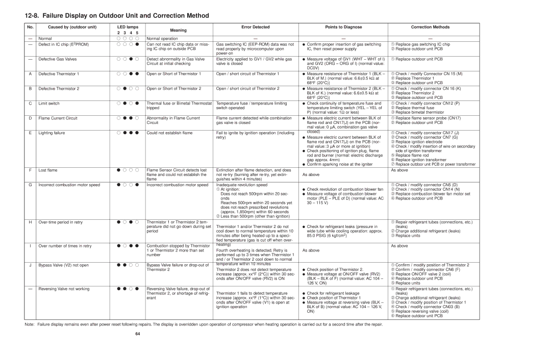
No. | Caused by (outdoor unit) | LED lamps | Meaning | Error Detected | Points to Diagnose | Correction Methods |
| | 2 | 3 | 4 | 5 | | | |
| | | | | |
| | | | | | |
— | Normal | ● ● ● ● | Normal operation | — | — | — |
| | | | | | |
— | Defect in IC chip (E 2PROM) | ● ● ● ● | Can not read IC chip data or miss- | Gas switching IC (EEP-ROM) data was not | ● Confirm proper insertion of gas switching | ➀ Replace gas switching IC chip |
| | | | | | ing IC chip on outside PCB | read properly by microcomputer upon | IC, then reset power supply | ➁ Replace outdoor unit PCB |
| | | | | | | power-on | | |
| | | | | | |
— | Defective Gas Valves | ● ● ● ● | Detect abnormality in Gas Valve | Electricity applied to GV1 / GV2 while gas | ● Measure voltage of GV1 (WHT – WHT of I) | ➀ Replace outdoor unit PCB |
| | | | | | Circuit at initial checking | valve is closed | and GV2 (ORG – ORG of I) (normal value: | |
| | | | | | | | DC0V) | |
| | | | | | |
A | Defective Thermistor 1 | ● ● ● ● | Open or Short of Thermistor 1 | Open / short circuit of Thermistor 1 | ● Measure resistance of Thermistor 1 (BLK – | ➀ Check / modify Connector CN 15 (M) |
| | | | | | | | BLK of M.) (normal value: 6.6±0.5 kΩ at | ➁ Replace Thermistor 1 |
| | | | | | | | 68°F (20°C)) | ➂ Replace outdoor unit PCB |
| | | | | | |
B | Defective Thermistor 2 | ● ● ● ● | Open or Short of Thermistor 2 | Open / short circuit of Thermistor 2 | ● Measure resistance of Thermistor 2 (BLK – | ➀ Check / modify connector CN 16 (K) |
| | | | | | | | BLK of K.) (normal value: 6.6±0.5 kΩ at | ➁ Replace Thermistor 2 |
| | | | | | | | 68°F (20°C)) | ➂ Replace outdoor unit PCB |
| | | | | | |
C | Limit switch | ● ● ● ● | Thermal fuse or Bimetal Thermostat | Temperature fuse / temperature limiting | ● Check continuity of temperature fuse and | ➀ Check / modify connector CN12 (P) |
| | | | | | tripped | switch operated | temperature limiting switch (YEL – YEL of | ➁ Replace thermal fuse |
| | | | | | | | P) (normal value: 1Ω or less) | ➂ Replace bimetal thermistor |
| | | | | | |
D | Flame Current Circuit | ● ● ● ● | Abnormality in Flame Current | Flame current detected while combination | ● Measure electric current between BLK of | ➀ Replace flame sensor probe (CN17) |
| | | | | | Circuit | gas valve is closed | flame rod and CN17(J) on the PCB (nor- | ➁ Replace outdoor unit PCB |
| | | | | | | | mal value: 0 µA, combination gas valve | |
| | | | | | | | | |
E | Lighting failure | ● ● ● ● | Could not establish flame | Fail to ignite by ignition operation (including | closed) | ➀ Check / modify connector CN17 (J) |
|
| | | | | | | retry) | ● Measure electric current between BLK of | ➁ Check / modify connector CN7 (G) |
| | | | | | | | flame rod and CN17(J) on the PCB (nor- | ➂ Replace ignition electrode |
| | | | | | | | mal value: 3 µA or more at ignition) | ➃ Check / modify insertion of wire on secondary |
| | | | | | | | ● Check positioning of ignition plug, flame | side of ignition transformer |
| | | | | | | | rod and burner (normal: electric discharge | ➄ Replace flame rod |
| | | | | | | | gap approx. 4mm) | ➅ Replace ignition transformer |
| | | | | | | | ● Confirm sparking noise at the igniter | ➆ Replace outdoor unit PCB or power transformer |
| | | | | | |
F | Lost flame | ● ● ● ● | Flame Sensor Circuit detects lost | Extinction after flame detection, and does | | As above |
| | | | | | flame and could not establish the | not re-try (burning after re-try, yet extin- | As above | |
| | | | | | flame | guishes within 4 minutes) | | |
| | | | | | |
G | Incorrect combustion motor speed | ● ● ● ● | Incorrect combustion motor speed | Inadequate revolution speed | | ➀ Check / modify connector CN5 (D) |
| | | | | | | ➀ At ignition: | ● Check revolution of combustion blower fan | ➁ Check / modify connector CN14 (N) |
| | | | | | | Does not reach 500rpm within 20 sec- | ● Measure voltage of combustion blower | ➂ Replace combustion blower fan motor set |
| | | | | | | onds | motor (PLE – PLE of D) (normal value: AC | ➃ Replace outdoor unit PCB |
| | | | | | | Reaches 500rpm within 20 seconds yet | 30 – 115 V) | |
| | | | | | | does not reach prescribed revolutions | | |
| | | | | | | (approx. 1,850rpm) within 60 seconds | | |
| | | | | | | ➁ Less than 500rpm (other than ignition) | | |
| | | | | | |
H | Over-time period in retry | ● ● ● ● | Thermistor 1 or Thermistor 2 tem- | | | ➀ Repair refrigerant tubes (connections, etc.) |
| | | | | | perature did not go down during set | Thermistor 1 and/or Thermistor 2 do not | ● Check for refrigerant leaks (pressure in | (leaks) |
| | | | | | period | cool down to normal temperature within 10 | wide tube while cooling operation: approx. | ➁ Charge additional refrigerant (leaks) |
| | | | | | | minutes after being heated up to a speci- | 85.0 PSIG (6 kgf/cm2) | ➂ Replace units |
| | | | | | | fied temperature (gas is cut off when over- | | |
| | | | | | | | | |
I | Over number of times in retry | ● ● ● ● | Combustion stopped by Thermistor | heating) | | As above |
| |
| | | | | | 1 or Thermistor 2 more than set | Fourth overheating is detected. Retry is | As above | |
| | | | | | number | performed up to 3 times when Thermistor 1 | | |
| | | | | | | and / or Thermistor 2 cool down to normal | | |
| | | | | | | | | |
J | Bypass Valve (V2) not open | ● ● ● ● | Bypass Valve failure or drop-out of | temperature within 10 minutes | | ➀ Confirm / modify position of Thermistor 2 |
| |
| | | | | | Thermistor 2 | Thermistor 2 does not detect temperature | ● Check position of Thermistor 2. | ➁ Confirm / modify connector CN6 (F) |
| | | | | | | increase (approx. xx°F (2°C)) within 30 sec- | ● Measure voltage at ON/OFF valve (RV2) | ➂ Replace ON/OFF valve 2 (coil) |
| | | | | | | onds after ON/OFF valve (RV2) is ON | (BLK – BLK of F) (normal value: AC 104 – | ➃ Replace outdoor unit PCB |
| | | | | | | | 126 V, ON) | ➄ Replace units |
| | | | | | |
— | Reversing Valve not working | ● ● ● ● | Reversing Valve failure, drop-out of | | | ➀ Repair refrigerant tubes (connections, etc.) |
| | | | | | Thermistor 2, or shortage of refrig- | Thermistor 1 fails to detect temperature | ● Check for refrigerant leakage | (leaks) |
| | | | | | erant | increase (approx. xx°F (1°C)) within 30 sec- | ● Check position of Thermistor 1 | ➁ Charge additional refrigerant (leaks) |
| | | | | | | onds after ON/OFF valve (V1) is open at | ● Measure voltage at reversing valve (BLK – | ➂ Check / modify position of Thermistor 1 |
| | | | | | | ignition operation | BLK of B) (normal value: AC 104 – 126 V, | ➃ Check / modify connector CN03 (B) |
| | | | | | | | ON) | ➄ Replace reversing valve (coil) |
| | | | | | | | | ➅ Replace outdoor unit PCB |
| | | | | | |
Note: | Failure display remains even after power reset following repairs. The display is overridden upon operation of compressor when heating operation is carried out for a second time after the repair. | |