400e, 410e specifications
The SATO 410e and 400e are advanced thermal transfer printers designed for high-performance label printing in a variety of industries, including retail, logistics, and manufacturing. These models are renowned for their reliability, efficiency, and quality output, making them essential tools for businesses that demand precision and durability in their labeling processes.One of the standout features of the SATO 410e and 400e is their exceptional print quality. They offer a resolution of up to 600 dpi, ensuring that even the most intricate details in barcodes, logos, and text are printed with clarity. This high resolution is crucial for applications that require precision, such as product labeling and inventory management.
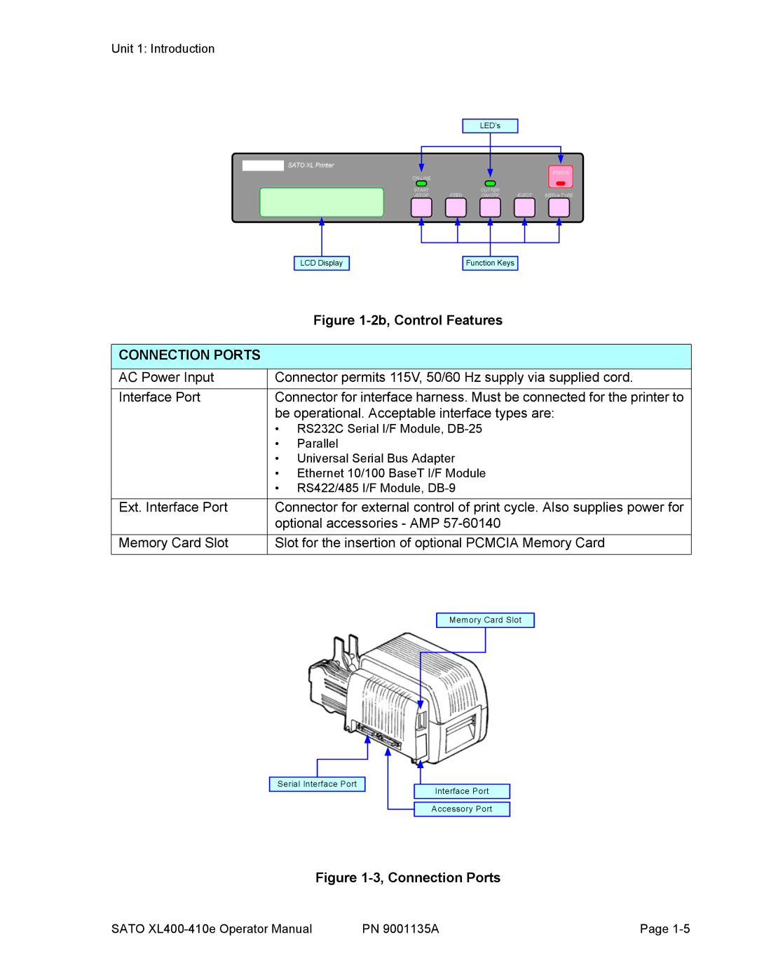
The SATO 410e is equipped with an intuitive user interface that simplifies operation. Its LCD display provides real-time information about print status, and its control panel is designed for ease of navigation, reducing the learning curve for new users. On the other hand, the SATO 400e emphasizes compact design without compromising performance, making it an ideal choice for businesses with limited space or needing a mobile labeling solution.
Both models feature a robust set of connectivity options, including USB, Ethernet, and serial interfaces, allowing for seamless integration into existing IT infrastructures. This versatility makes them suitable for various deployment scenarios, whether used standalone or in networked environments.
In terms of speed, the SATO 410e and 400e are engineered to deliver rapid printing capabilities. The 410e can produce labels at a speed of up to 300 mm per second, while the 400e also showcases impressive speed without sacrificing quality. This capability is vital for high-volume printing tasks common in warehousing and distribution operations.
The technology behind these printers includes SATO’s innovative ARCP (Automatic Ribbon Control Path), which optimizes ribbon usage and minimizes waste, contributing to cost-effective printing solutions. Additionally, the SATO 410e and 400e support a wide range of media types and sizes, accommodating various labeling needs from small tags to large shipping labels.
Both models are also designed with durability in mind. They are built to withstand the rigors of industrial environments, ensuring longevity and consistent performance. With features like a strong casing and reliable internal components, users can expect these printers to maintain operational integrity even under demanding conditions.
In conclusion, the SATO 410e and 400e represent the pinnacle of label printing technology, combining high print quality, user-friendly interfaces, efficient connectivity, and robust performance. These printers are perfect for businesses looking to enhance their labeling processes and achieve operational excellence in their respective fields.

