Printer
Sato America, Inc
Table of Contents
Troubleshooting
Printer Configuration
Appendix
Maintenance
Offset
Introduction
Equipment Damage
About this Manual
1a, Primary Components
General Description
Operator Panel Features LED Definition
Control Features
Operator Panel
Technical Data
Processing
Physical Characteristics
Power
Environmental
Ribbon
Command
Sensing
Media
Character Font Capabilities
Postnet
Barcode Capabilties
UPC A/E
MSI
Installation
Unpacking & Parts Identification
Unpacking & Parts Identification
Site Location
Printer Installation
Cable Connection
Media & Ribbon Loading
Media Selection
3b, Fan-fold Media Loading
TEAR-OFF Mode
Operational Mode Selection
Continuous Mode
Label Print Direction
RS232C HIGH-SPEED Serial Interface
Interface Specifications
Accessories Installation unit for guidance
Interface Selection
OFF ON/X-OFF
PIN Direction Signal Definition
OFF
OFF ODD Even None
ON/X-OFF Cable Requirements
READY/BUSY Cable Requirements DB9
Host Direction
Printer
ACK
Specifications
PIN Assignments Signal Direction
IEEE1284 Parallel Interface
Local Area Network LAN Ethernet
Dipswitch Settings
Setting
Universal Serial BUS USB
Accessory EXT Connector PIN Assignments
Software Specifications
Direction Signal Definition
Ssid
802.11G Wireless
Switch Setting
LED Indicator Status Description
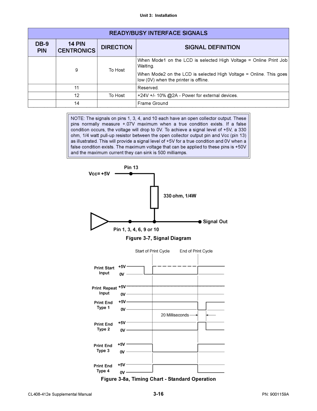
READY/BUSY Interface Signals
EXT Accessory Port
+24V +/- 10% @2A Power for external devices
Low 0V when the printer is offline
Waiting
8b, Timing Chart Repeat Print
ALL Interfaces
Interface Signals
Cable Requirements
50 of 500 items in the history buffer
Receive Buffer Control
Interface Installation
Accessories Installation
Printer Configuration
Unit 4 Printer Configuration
DSW1 Default Settings
Dipswitch Settings
DSW1 Configuration
Function Description
Configuration
DSW1 Function
DSW3 Default Settings
Normal Mode
Configuration Modes
Advanced Mode
Advanced Mode
User Download Mode
User Download Mode
Service Mode
Service Mode
Card Mode
Card Mode
DSW7 on Line + Feed + Power
Protocol Initialization Mode
Counters Mode
Counters Mode
Test Print Mode
Test Print Mode
Yes
Boot Download Mode
10, Flash Memory Download Mode
Flash Memory Download Mode
11, Default Setting Mode
Default Setting Mode
Online QTY
HEX Dump Mode
13, Maintenance Mode
Maintenance Mode
Menu Description
Normal Mode Table
Advanced Mode Table
Menu Definition Tables
Proportional is contemporarily preferred
Real-time clock is not installed
Point respectively
Stream including graphics and 2D barcodes
Service Mode Table
Operator to manage the expanded memory card
As most important where conflicting data exists
Is only a transitional menu screen for the Service Mode
Languages are provided as options
Card Mode Table
Allows the selection of which counter to be viewed to reset
Transitional menu screen to access the Counters Mode
Or use
Font The contents of the installed fonts
Is the initial screen of the Test Print Mode
Configuration The printer’s configuration settings
Barcode The printer’s installed barcodes
Reboot the printer to return to normal operation
Also prompts the operator on how to proceed
Select the Interface option for a standard download
Clear its Eeprom of all data
To proceed to the Factory Mode
Print buffer
Clear
Page. These are the only two options
Maintenance Mode Table
Troubleshooting
Error Signal Troubleshooting
Troubleshooting Table
Smeared Print Images
No Printed Image
Printer Creates a Blank Label
Incorrect Label Positioning
CHK Troubleshooting Step
Interface Troubleshooting
LAN Ethernet Interface
Power
Test Print Troubleshooting
Test Label Printing
Sample Test Label
Maintenance
PRINTER, Excersize Care to Prevent Print Head Damage
Cleaning Procedures
Print Head Replacement
Replacement Procedures
1b, Print Head Replacement
Interface Board Replacement
Interface Board Replacement
Fuse Replacement
Fuse Replacement
Print Head Balance Adjustment
Adjustment Procedures
5a, Print Head Alignment
Print Head Alignment
Head Balance and Print Head Alignment
Ribbon Guide Alignment
Label Sensor Positioning
Label Sensor Positioning
Ribbon Spindle Tensioning
Ribbon Spindle Tensioning
Potentiometer DESCRIPTION/PROCEDURE
Operational Adjustments
Darkness
Print Base Reference Position
Appendix
Direction
Print Setup Dimensions
Label Reference Position
Label Reference Position Diagram
Glossary
Glossary
Ascii
Half. The core is convexed and the cavity is concaved
Bytes Collection of 8 bits used in the binary system
Being its mating half
Is a plug male and the other is a socket female
Data transmission, seven additional bits are required
DPI
Dram
Eeprom
To attach two or more objects
Power
Tag would typically have to be removed from its object
Next label for printing
LED
LCD
Or voltage divider Primary
Potentiometer
Rfid
RAM
RF/AIS
RF/DC
Sbpl
ROM
RPM
SAM
Sram
Glossary