| Unit 3: Installation |
|
|
| SOFTWARE SPECIFICATIONS |
|
|
Corresponding Protocol | TCP/IP |
|
|
Network Layer | ARP, RARP, IP, ICMP |
|
|
Session Layer | TCP, UDP |
|
|
Application Layer | LPD, FTP, TELNET, BOOTP, DHCP |
|
|
NOTE: Print data can be sent by LPR and FTP of TCP/IP and dedicated socket protocol. Printer status is obtainable by dedicated socket protocol.
NOTE: In the TCP/IP protocol enviroment, LPD and FTP are provided for printing; TELNET for variable setup; ARP, RARP, and BOOTP/DHCP for address setup.
LPD protocol complies with RFC1179 and handles the list of logical printer name as queue name such as lp, sjis, euc. In addition, a banner page can be printed by a proper setup.
When sending the job by LPR, the transmission order of data file/control file within the job will not affect print operation. In addition, if the banner page is specified, it will be added to each data file. Job deletion by LPR is not available.
FTP protocol complies with RFC959 and handles the list of logical printer name as a transfer directory. File transfer to this directory executes print operation. It is possible to specify ASCII(A), Binary(I) and TENEX(L8) as transfer mode - although the mode difference is dependent on the client. A banner page may be printed with a proper setup.
TELNET Complies with RFC854. This operation consists of interactive menu form and enables change and reference of internal setup, and to display status. To change the setup, enter “root” user and password at the time of login. Default of root pasword is set as null (linefeed only).
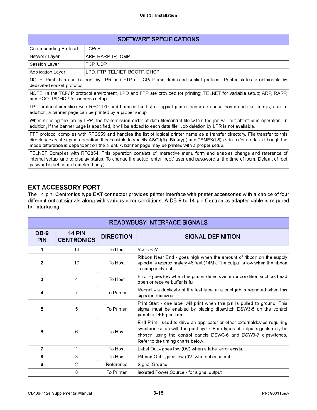
EXT ACCESSORY PORT
The 14 pin, Centronics type EXT connector provides printer interface with printer accessories with a choice of four different output signals along with various error conditions. A
READY/BUSY INTERFACE SIGNALS
14 PIN | DIRECTION | SIGNAL DEFINITION | ||
PIN | CENTRONICS | |||
|
|
|
| |
1 | 13 | To Host | Vcc | |
|
|
|
| |
|
|
| Ribbon Near End - goes high when the amount of ribbon on the supply | |
2 | 10 | To Host | spindle is approximately 46 feet (14M). The output is low when the ribbon | |
|
|
| is completely out. | |
3 | 4 | To Host | Error - goes low when the printer detects an error condition such as head | |
open or receive buffer is full. | ||||
|
|
| ||
|
|
|
| |
4 | 7 | To Printer | Reprint - a duplicate of the last label in a print job is reprinted when this | |
signal is received. | ||||
|
|
| ||
|
|
|
| |
|
|
| Print Start - one label will print when this pin is pulled to ground. This | |
5 | 5 | To Printer | signal must be enabled by placing dipswitch | |
|
|
| panel to OFF position. | |
|
|
|
| |
|
|
| End Print - used to drive an applicator or other externaldevice requiring | |
6 | 6 | To Host | synchronization with the print cycle. Four types of output signals may be | |
chosen using the control panels | ||||
|
|
| ||
|
|
| Refer to the timing charts below. | |
|
|
|
| |
7 | 1 | To Host | Label Out - goes low (0V) when a label error exists. | |
|
|
|
| |
8 | 3 | To Host | Ribbon Out - goes low (0V) whe ribbon is out. | |
|
|
|
| |
9 | 2 | Reference | Signal Ground. | |
|
|
|
| |
| 8 | To Printer | Isolated Power Source - for signal output. | |
|
|
|
|
PN: 9001159A |