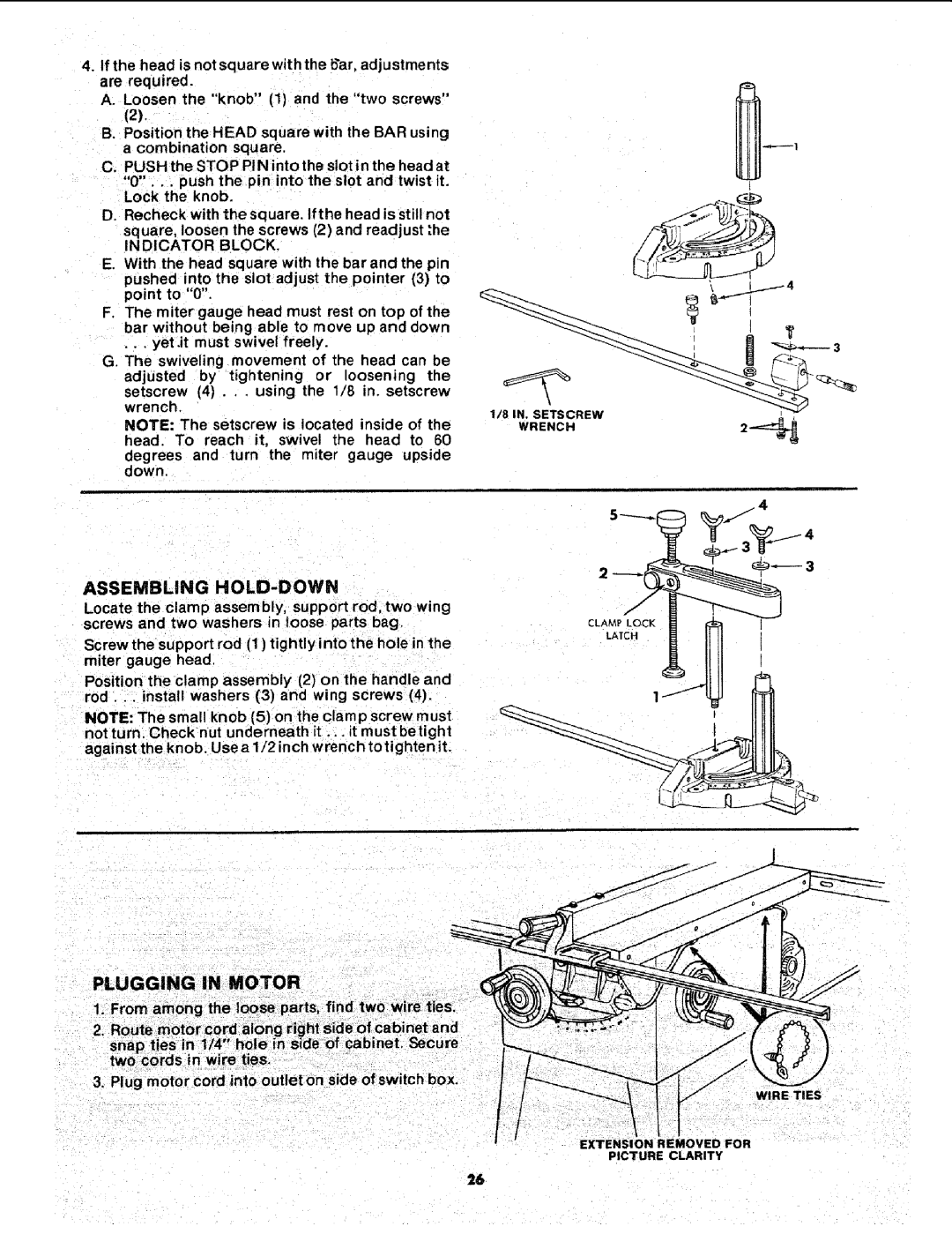
4.If the head is not square with the bar, adjustments are required.
A. Loosen the "knob" (1) and the "two screws"
(2).
B.Position the HEAD square with the BAR using a combination square.
C.PUSH the STOP PIN into the slot in the head at "0"... push the pin into the slot and twist it. Lock the knob.
D.Recheck with the soluare. If the head is still not square, loosen the screws (2) and readjust t.he iNDiCATOR BLOCK.
E.With the head square with the barand the pun
pushed into the slot adjust the pointer (3) to point to "0".
F.The miter gauge head must rest on top of the bar without being able to move up and down •. , yet.it must swivel freely.
G.The swiveling movement of the head can be adjusted by tightening or loosening the
setscrew (4) . . . using the 1/8 in. setscrew wrench.
NOTE: The setscrew is located inside of the head. To reach it, swivel the head to 60
degrees and turn the miter gauge upside down.
1/8 IN. SETSCREW
WRENCH
ASSEMBLING HOLD-DOWN
Locate the clamp assembly, support rod, two wing screws and two washers in loose parts bag.
Screw the support rod (1) tightly into the hole in the miter gauge head.
Position the clam p assembly (2) on the handle and rod .. install washers (3) an(_ wing screws (4).
NOTE: The sma!l knob (5) on the clamp screw must not turn. Check nut underneath it ... it must betight
against the knob. Use a 1/2 inch wrench to tighten it.
PLUGGING IN MOTOR
1.From among the loose parts, find two wire tieS.
2.Route motor cord along right side of cabinet and
snap ties in 1/4" hole in stde of cabinet. Secure two cords in wire ties.
3.Plug motor cord into outlet on side of switch box.
I
WIRE TIES
PICTURE CLARITY
26