HEX SCREWS
FENCE HEAD
3, The rip fence must be PARALLEL with the
sawblade and miter Gauge grooves Move fence until it is along side of groove. E)o NOT
LOCK IT. It sPiou/d be parallel to groove, If it rs not;
A. Loosen the two "Hex Head Screws."
B. Hold fence head tightly against bar.. move end of fence so that it is parallel with groove.
C. Alternately tighten the screws,
\
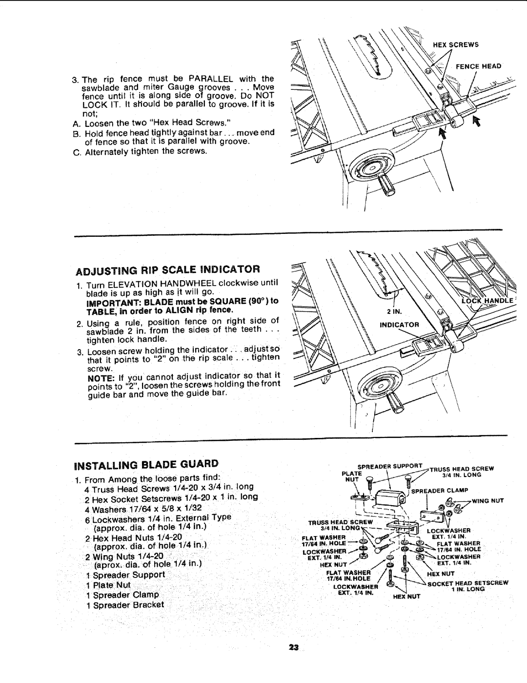
ADJUSTING RiP SCALE iNDiCATOR
1.Turn ELEVATION HANDWHEEL clockwise until blade is up as high as it will go.
IMPORTANT: BLADE must be SQUARE (90 °) to
TABLE, in order to ALIGN rip fence,
2.Using a rule, position fence on right side of sawblade 2 in. from the sides of the teeth...
tighten lock handle,
3.Loosen screw holding the indicator.., adjust so that it points to "2" on the rip scale.., tighten screw.
NOTE: If you cannot adjust indicator so that it poin ts to "2", loosen the screws holding the front guide bar and move the guide bar.
iNSTALLING BLADE GUARD
1.From Among the loose parts find:
4 Truss Head Screws
6 Lockwashers 1/4 in. External Type (approx, die. of hole 1/4 in.)
2 Hex Head Nuts
2 Wing Nuts
(aprox, dia. of hole 1/4 in.)
1 Spreader Support
1 Plate Nut
1 Spreader Clamp
1 Spreader Bracket
\
\
| SPREADER | SUPPORT |
|
|
| PLATE |
|
|
|
| NUT |
|
|
|
|
| SPREAOER | CLAMP |
|
|
|
|
| NUT |
FLAT WASHER | EXT. 1/4 IN. | |||
17_41N |
| |||
| FLAT | WASHER | ||
|
| |||
|
|
| IN. | HOLE |
EXT. IN | IN. |
|
|
|
HEX | NUT | EXT, | !/4 | tN. |
| / | |||
FLAT WASHER | NUT |
| ||
17/64 IN.HOLE |
| |||
|
|
| ||
|
| ,OCKET | HEAD SETSCREW | |
| EXT. 1/4 IN. | HEX NUT | 1 If_. LONG | |
|
|
|
| |
23