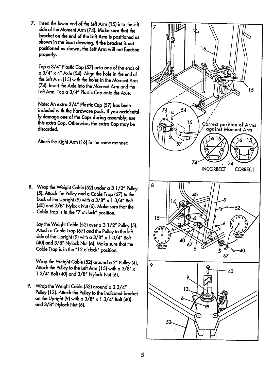
. Insert the lower enc[of the LeftArm (15) into the left side of the Moment Ann (74). Make sure that the bracket on the end of the LeftArm is positionedas shown in the insetdrawing. If the bracket is nat positioned as shown, the LeftAnn willnot function
properly.
Top a 3/4" PlasticCap (57) onto one of the ends of a 3/4" x 4" Axle (54). Align the hole in the end of the LeftArm (15} with the holes in the Moment
(74). Insert the Axle into the Moment Arm and the LeftArm. Tap a 3/4' PlasticCap onto the Axle.
Nole: An extra 3/4" Plastic Cap (57) has been included with the hardware pock. If you accldenlal- ly damage one of He Caps during assembly, use this extra Cap. Otherwise, the extra Cap may be discarded.
Attach the Right Arm (16) in the same manner.
8
8.Wrap the Weight Cable (52) under a 3 1/2" Pub/ 15).Attach the Pulleyand a Cable Trap (67) to the
back of the Upright (9) with a 3/8" x 1 3/4" Bolt (40) and 3/8" Nylock Nut (6). Make sure that the Cable Trap is in the "7 o°dock" position.
Laythe Weight Cable (52) over a 3 1/2' Pulley(51.
_toch o Cable Trap (67) and the Pulley to the I_ side of the Upright (9) with a 3/8" x 1 3/4" Bolt
(40) and 3/8" Nylock Nut (6). Make sure that the Cable Trap is in the "12 o'cbck"position.
Wrap | the Weight Cable (52) around a 2" Pulley(4). | 9 |
h'_ch the Pulleyto the LeftAnn (15} with a 3/8" x |
| |
1 3/4" | Bolt (40} and 3/8" Nylock Nut (6). |
|
9.Wrap the Weight Cable (52} around a 2 3/4"
Pulley1131.,_ach the Pulleyto the indicated bracket on the Upright 19) with a 3/8" x 1 3/4" Bolt(40) and 3/8" Ny!ock Nut (6).
15
,/"
/ | [ |
/
C_rrect position of Arms
against Moment Arm
74
INCORRECI" CORRECT
5