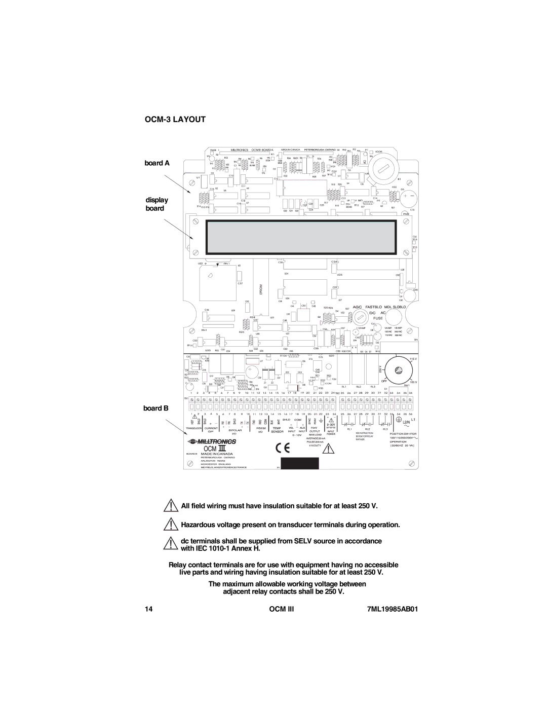
OCM-3 LAYOUT
board A
display board
board B
![]() All field wiring must have insulation suitable for at least 250 V.
All field wiring must have insulation suitable for at least 250 V.
![]() Hazardous voltage present on transducer terminals during operation.
Hazardous voltage present on transducer terminals during operation.
dc terminals shall be supplied from SELV source in accordance with IEC
Relay contact terminals are for use with equipment having no accessible live parts and wiring having insulation suitable for at least 250 V.
The maximum allowable working voltage between adjacent relay contacts shall be 250 V.
14 | OCM III | 7ML19985AB01 |