Open channel
Contact Smpi Technical Publications at the following address
Unit Repair and Excluded Liability
Table of Contents
General Keypad Initial Start Up Fundamental Checks
Start UP
Operation
Appendices
Maintenance Error Codes 100 Communications 101 7ML19985AB01
OCM
Short
About this
If you want to know about Read Product
OCM
» range 20 or 4-20 mA » resolution
Specifications
» 20 to 50 C -5 to 122 F
IP65 enclosure
» CE *, FM, CSA NRTL/C
Programmer
Transducer
Temperature Sensor
Cabling
Auxiliary Input
Communication Software
Output » Belden
Installing the OCM-3
Installation
Outline and Mounting
OCM-3 Layout
OCM-3
System Diagram
Customer device
Installing the Temperature Sensor
Installing the Transducer
Ground shield at OCM-3 only Basic Wiring Temperature Sensor
Ground shield at OCM-3 only
Relays
MA Output
Synchronization
AC Power
Power Connections
DC Power
Installing the Programmer
Installing the Memory BACK-UP Battery
Disconnect power before installing or replacing the battery
Communicating VIA Computer
General
Start UP
Keypad
OCM-3 is asking which language you prefer to communicate
Initial Start UP
Language
English
F13 auto zero calibration 160 Completed 7ML19985AB01
P0 language English P1 dimensional units Centimeters
24-hr. time
1141
114100 Enter new time
F5 ddmmyyyy date October 12
Fundamental Checks
OCM
Memory
Operation
Security
Units
Display
Flow Calculation
Absolute vs. ratiometric
= constant
Damping
For battery operation, set display lighting to off or auto
Example For relay
For battery operation, have relays energizing on alarm
» 20 mA
» P6 * flow rate
Flow Rate and Totalizing
FAIL-SAFE
Flow rate
Capacity
Logging
Viewing the data log
Blanking
Temperature
Time and Date
Reset
Emulation Mode
Auxiliary Head Input
Flow Velocity Input
Voltage Input Current Input
As normal 7ML19985AB01
DC Output
Diagnostic Aids
100% head 4 m, enter 5 m
‘D’ Parameter Listing
Security access required
Velocity
Nominal target range
OCM
‘F’ Parameter Listing
Enter security code Emulation mode
Keypad to mA output
OCM
Linear Velocity
‘P’ Parameter Listing
= centimetres
= absolute = ratiometric Flow rate units
Flowrate Volume
Gallons
= imperial million gallons per day
OCM
= 4-20 mA = 0-20 mA 7ML19985AB01
OCM
OCM
Variable condition
Fixed
Units
OCM
‘U’ Parameters for P3 Primary Element
OCM
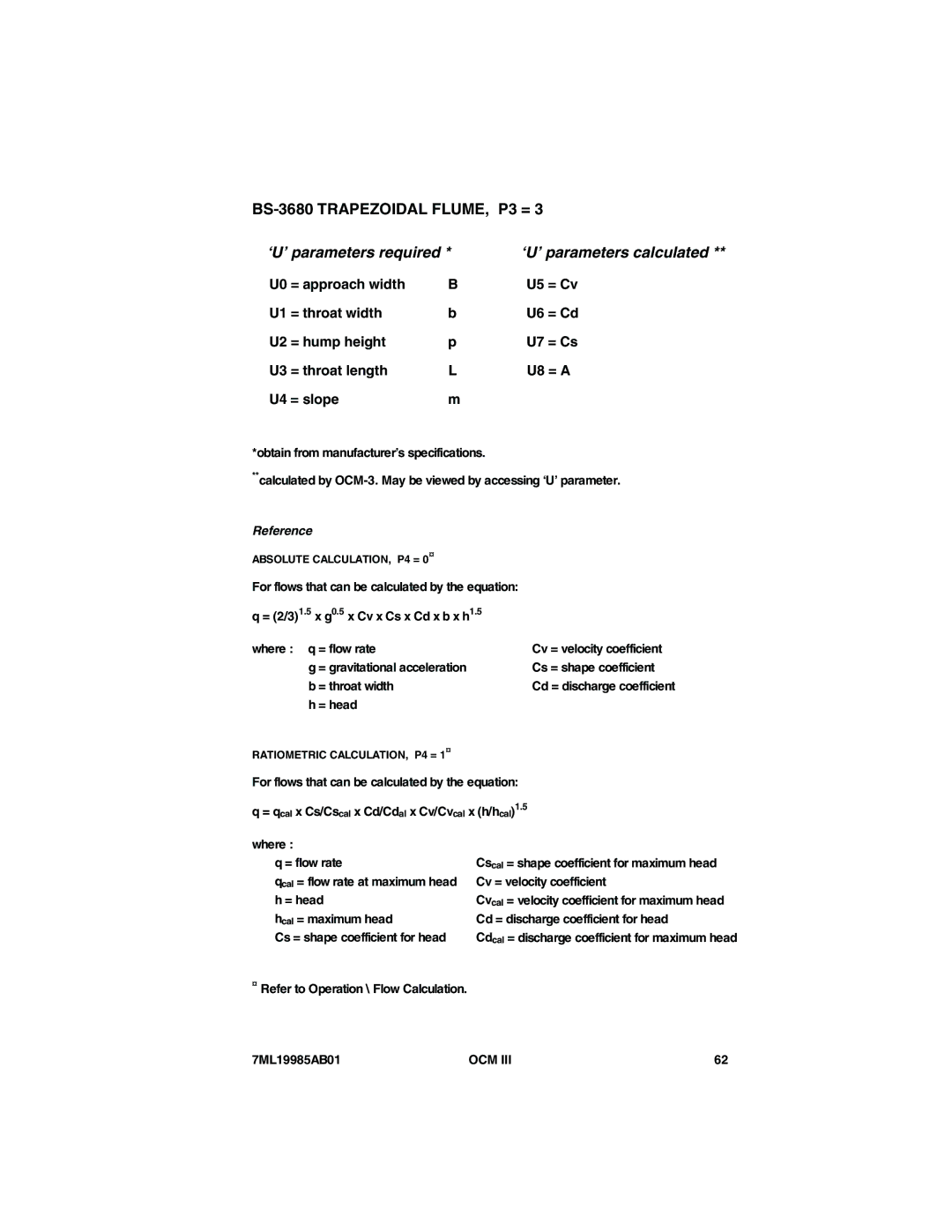
Reference
U0 = exponent U1 = k factor P4 = 0 only
= constant factor U1 = head
Typical Weir Profiles
Typical SHARP-CRESTED Weirs
Khafagi Venturi
Typical Parshall Flume
Typical Leopold Lagco
‘U’ parameters required ‘U’ parameters calculated
BS-3680 Rectangular Flume
= crest width = Cv = crest height = Cd = crest length = a
BS-3680 Round Nose Horizontal Crest Weir
¤ Refer to Operation \ Flow Calculation 7ML19985AB01
Cv = velocity coefficient
BS-3680 Trapezoidal Flume
BS-3680 U-Flume, P3 =
BS-3680 U-FLUME
= head H and p applied to C
= crest width = C = crest height = Cp = crest length
BS-3680 Finite Crest Weir
= approach width = Ce = crest width = K b = crest height
= Ce x 2⁄3 ⎯⎯√2⎯g x be x he1.5 Where q = flow rate
= gravitational acceleration
= crest width He = effective head h + Kh = head Kh = 1 mm
BS-3680 Thin Plate Rectangular Weir
U0 = notch angle Alpha U1 = Ce
BS-3680 Thin Plate V-NOTCH Weir
U0 = crest width b
Rectangular Weir Contracted
= hydraulic radius = slope of hydraulic gradient
Based on the Manning Formula
Round Pipe
U0 = maximum flume width, hmax
PALMER-BOWLUS Flume
U0 = maximum listed head, hmax
Flume
U0 = number of data points n, 4 to
Universal Head vs FLOW, P3 =
Flow, point A15 Head, point A16
Flow, point A13 Head, point A14
Flow, point A17 Head, point A18
Flow, point A19
U0 = channel width B U1 = area h
Rectangular Area X Velocity
= head, cm = flow velocity, cm/sec
Trapezoidal Area X Velocity
For h ≥ d
= B b/d Where q = flow rate, l/s
= channel top width, cm = head, cm = channel base width, cm
Modified Trapezoidal Area X Velocity
U0 = base diameter D U1 = area h
Channel Area x Velocity
U0 = conduit diameter U1 = area h
Circular Area X Velocity
GULL-WING Area X VELOCITY, P3 =
Gull Wing Area X Velocity
EGG-SHAPED Area X VELOCITY, P3 =
EGG-SHAPED Area X Velocity
Typical open channel
Universal Area X VELOCITY, P3 =
Area Head
Universal Area X Velocity
A10 =
OCM
Maintenance
Error Codes
Computer
Customer’s
Serial printer
102
Protocol for the OCM-3 is as follows Baud rate
DB-25 connector
DB-9 connector
Bipolar Current
Refer to Cvcc Instruction
P35 = 7, print interval set for 7 minutes
Date
104
Remote OCM-3 display Local display
Utilities Software Programmer Remote OCM-3 programming
105
106
Display value
Typical OCM-3
00.000000 99.12399.123000 7ML19985AB01
107
Response
# = 0 through Content of P5
Stop data log down load
Start data log down load
109
Standard modem
DB-25 connector 7ML19985AB01
Cable
Computer Telephone lines Remote modem
Connect
Establishing Communication
111
112
Ending Communication
Rev