FLOW VELOCITY INPUT
In some applications, the flow calculation for the chosen primary element requires a velocity input. In this type of application, the transducer measurement is used to calculate the cross sectional area of the flow. By multiplying the area with the distance per time units of velocity, the volume per time units of flow are calculated. The calculated velocity can be viewed via D8.
The 0% and 100% limits of the velocity input must be scaled using parameters P8 and P9.
»select P8
»enter the voltage corresponding to zero velocity
»select P9
»enter the velocity corresponding to 5 V
e.g. | If the velocity sensor output is 1 V per m/sec and the output is |
| scaled for 7 V at 100% velocity (7 m/sec), then enter 5 m/sec. If the |
| output is scaled for 4 V at 100% velocity (4 m/sec), enter 5 m/sec. |
P8 and P9 can only be accessed if P3 has been set for an option that requires the use of a velocity input. The input voltage level can be viewed via D12.
|
|
|
|
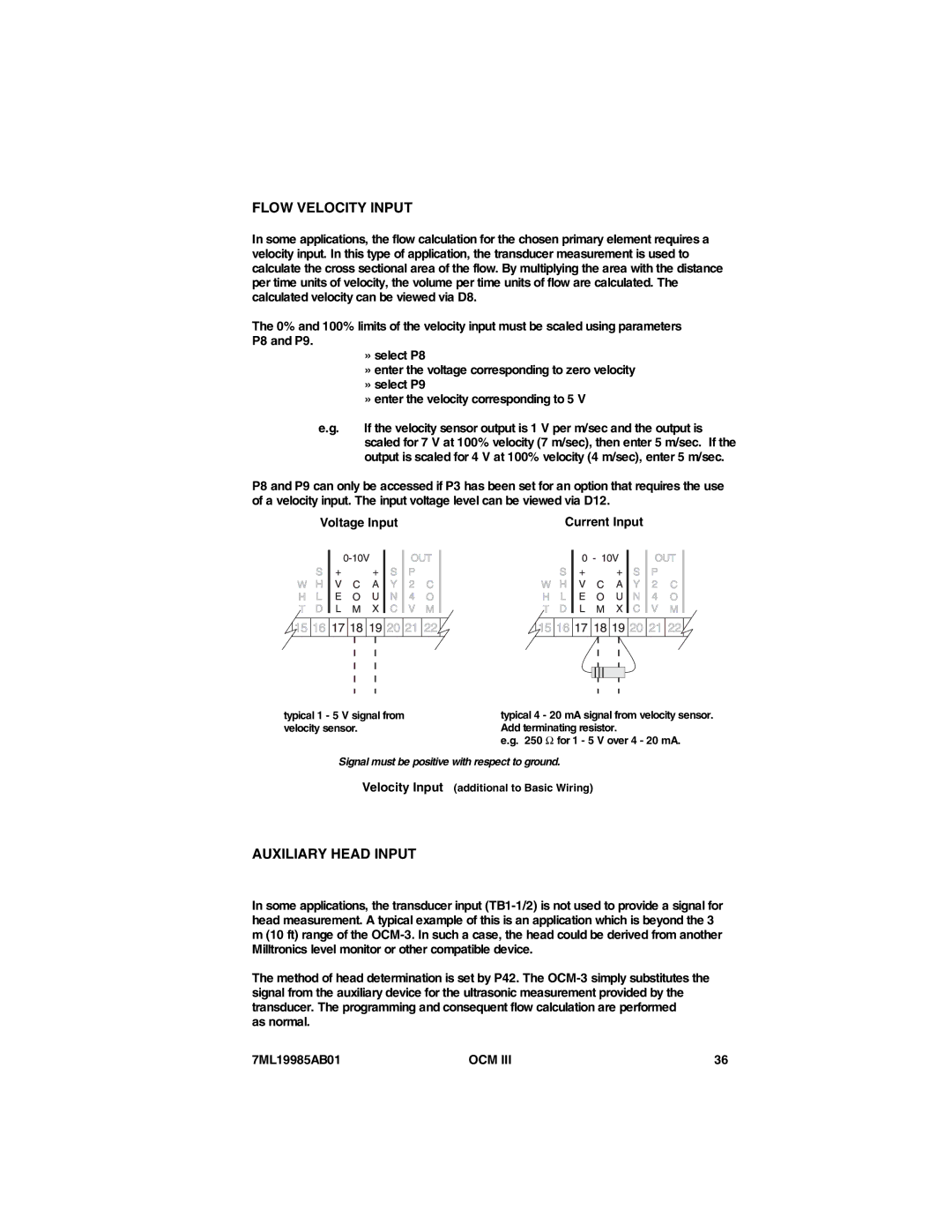
| Voltage Input |
|
|
|
|
|
|
| Current Input |
| ||||||||||||||||||||||
|
|
|
|
|
|
|
|
|
|
|
|
|
|
|
|
|
|
|
|
|
|
|
|
|
|
|
|
|
|
|
|
|
|
|
|
|
|
|
|
|
|
|
|
|
|
|
|
|
|
|
|
|
|
|
|
|
|
|
|
|
|
|
|
|
|
|
|
|
|
|
|
|
|
|
|
|
|
|
|
|
|
|
|
|
|
|
|
|
|
|
|
|
|
|
|
|
|
|
|
|
|
|
|
|
|
|
|
|
|
|
|
|
|
|
|
|
|
|
|
|
|
|
|
|
|
|
|
|
|
|
|
|
|
|
|
|
|
|
|
|
|
|
|
|
|
|
|
|
|
|
|
|
|
|
|
|
|
|
|
|
|
|
|
|
|
|
|
|
|
|
|
|
|
|
|
|
|
|
|
|
|
|
|
|
|
|
|
|
|
|
|
|
|
|
|
|
|
|
|
|
|
|
|
|
|
|
|
|
|
|
|
|
|
|
|
|
|
|
|
|
|
|
|
|
|
|
|
|
|
|
|
|
|
|
|
|
|
|
|
|
|
|
|
|
|
|
|
|
|
|
|
|
|
|
|
|
|
|
|
|
|
|
|
|
|
|
|
|
|
|
|
|
|
|
|
|
|
|
|
|
|
|
|
|
|
|
|
|
|
|
|
|
|
|
|
|
|
|
|
|
|
|
|
|
|
|
|
|
|
|
|
|
|
|
|
|
|
|
|
|
|
|
|
|
|
|
|
|
|
|
|
|
|
|
|
|
|
|
|
|
|
|
|
|
|
|
|
|
|
|
|
|
|
|
|
|
|
|
|
|
|
|
|
|
|
|
|
|
|
|
|
|
|
|
|
|
|
|
|
|
|
|
|
|
|
|
|
|
|
|
|
|
|
|
|
|
|
|
|
|
|
|
|
|
|
|
|
|
|
|
|
|
|
|
|
|
|
|
|
|
|
|
|
|
|
|
|
|
|
|
|
|
|
|
|
|
|
|
|
|
|
|
|
|
|
|
|
|
|
|
|
|
|
|
|
|
|
|
|
|
|
|
|
|
|
|
|
|
|
|
|
|
|
|
|
|
|
|
|
|
typical 1 - 5 V signal from | typical 4 - 20 mA signal from velocity sensor. |
velocity sensor. | Add terminating resistor. |
| e.g. 250 Ω for 1 - 5 V over 4 - 20 mA. |
Signal must be positive with respect to ground.
Velocity Input (additional to Basic Wiring)
AUXILIARY HEAD INPUT
In some applications, the transducer input
The method of head determination is set by P42. The
as normal.
7ML19985AB01 | OCM III | 36 |