Table 18. J13 Pin out Connector
PIN SIGNAL
1 | +VDD |
2 | N.C. |
3GND
J18 for Ethernet
The SpacePC 1232 module features a
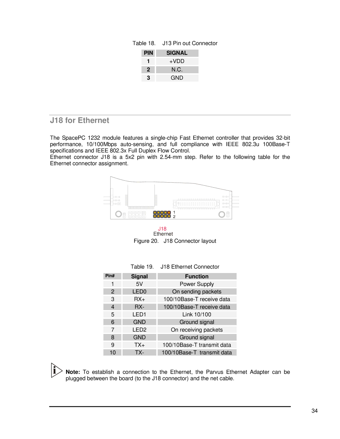
Ethernet connector J18 is a 5x2 pin with
|
| J18 |
|
| Ethernet |
| Figure 20. J18 Connector layout | |
| Table 19. J18 Ethernet Connector | |
Pin# | Signal | Function |
1 | 5V | Power Supply |
2 | LED0 | On sending packets |
3 | RX+ | |
4 | RX- | |
5 | LED1 | Link 10/100 |
6 | GND | Ground signal |
7 | LED2 | On receiving packets |
8 | GND | Ground signal |
9 | TX+ | |
10 | TX- | |
![]()
![]() Note: To establish a connection to the Ethernet, the Parvus Ethernet Adapter can be plugged between the board (to the J18 connector) and the net cable.
Note: To establish a connection to the Ethernet, the Parvus Ethernet Adapter can be plugged between the board (to the J18 connector) and the net cable.
34
