15
J1 and J2 for the ISA Bus
The ISA BUS
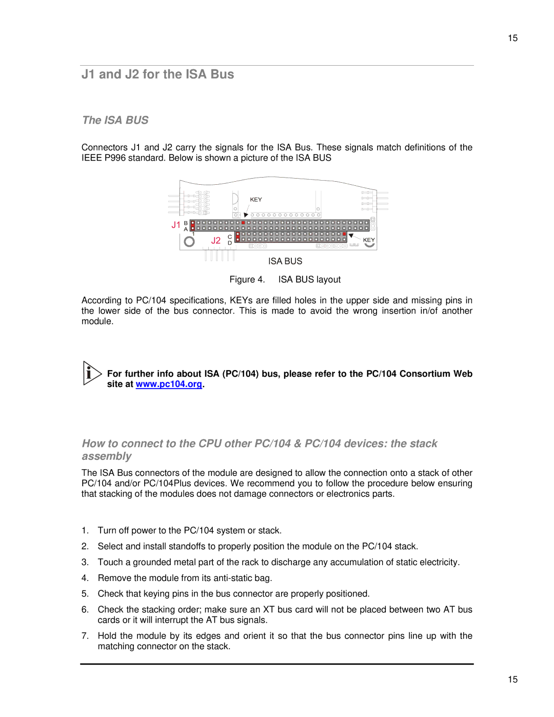
Connectors J1 and J2 carry the signals for the ISA Bus. These signals match definitions of the IEEE P996 standard. Below is shown a picture of the ISA BUS
Figure 4. ISA BUS layout
According to PC/104 specifications, KEYs are filled holes in the upper side and missing pins in the lower side of the bus connector. This is made to avoid the wrong insertion in/of another module.
![]()
![]()
![]() For further info about ISA (PC/104) bus, please refer to the PC/104 Consortium Web
For further info about ISA (PC/104) bus, please refer to the PC/104 Consortium Web
site at www.pc104.org.
How to connect to the CPU other PC/104 & PC/104 devices: the stack assembly
The ISA Bus connectors of the module are designed to allow the connection onto a stack of other PC/104 and/or PC/104Plus devices. We recommend you to follow the procedure below ensuring that stacking of the modules does not damage connectors or electronics parts.
1.Turn off power to the PC/104 system or stack.
2.Select and install standoffs to properly position the module on the PC/104 stack.
3.Touch a grounded metal part of the rack to discharge any accumulation of static electricity.
4.Remove the module from its
5.Check that keying pins in the bus connector are properly positioned.
6.Check the stacking order; make sure an XT bus card will not be placed between two AT bus cards or it will interrupt the AT bus signals.
7.Hold the module by its edges and orient it so that the bus connector pins line up with the matching connector on the stack.
15