63
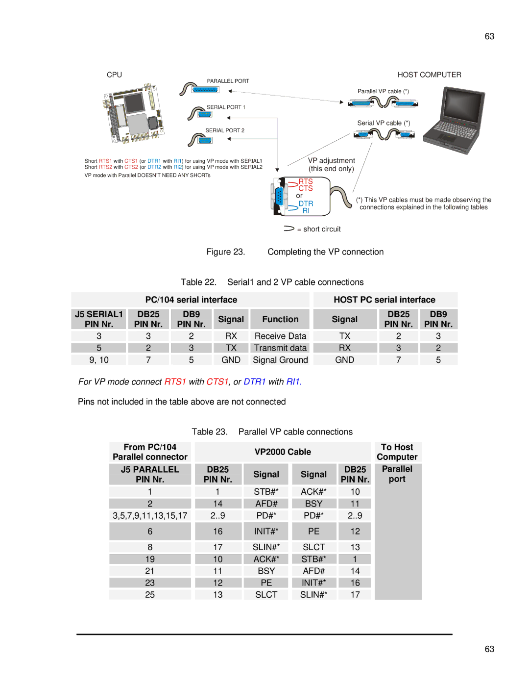
CPU
PARALLEL PORT
SERIAL PORT 1
SERIAL PORT 2
HOST COMPUTER
Parallel VP cable (*)
Serial VP cable (*)
Short RTS1 with CTS1 (or DTR1 with RI1) for using VP mode with SERIAL1 Short RTS2 with CTS2 (or DTR2 with RI2) for using VP mode with SERIAL2
VP mode with Parallel DOESN’T NEED ANY SHORTs
VP adjustment (this end only)

 RTS
RTS
![]() CTS or
CTS or
DTR  RI
RI
![]() = short circuit
= short circuit
(*)This VP cables must be made observing the connections explained in the following tables
Figure 23. Completing the VP connection
Table 22. Serial1 and 2 VP cable connections
PC/104 serial interface
| J5 SERIAL1 |
| DB25 |
| DB9 |
| Signal |
| Function |
|
|
|
|
|
|
| |||||
| PIN Nr. |
| PIN Nr. |
| PIN Nr. |
|
|
| ||
|
|
|
|
|
|
|
| |||
|
|
|
|
|
|
|
|
|
| |
| 3 | 3 | 2 |
| RX |
| Receive Data |
| ||
|
|
|
|
|
|
|
|
|
| |
| 5 |
| 2 |
| 3 |
| TX |
| Transmit data |
|
|
|
|
|
|
|
|
|
|
| |
| 9, 10 | 7 | 5 |
| GND |
| Signal Ground |
| ||
HOST PC serial interface
Signal | DB25 | DB9 | |
PIN Nr. | PIN Nr. | ||
| |||
TX | 2 | 3 | |
RX | 3 | 2 | |
GND | 7 | 5 |
For VP mode connect RTS1 with CTS1, or DTR1 with RI1.
Pins not included in the table above are not connected
|
| Table 23. | Parallel VP cable connections |
|
|
| |||||||
|
|
|
|
|
|
|
|
|
|
|
|
|
|
| From PC/104 |
|
|
|
| VP2000 Cable |
|
| To Host | ||||
| Parallel connector |
|
|
|
|
|
|
| Computer | ||||
|
|
|
|
|
|
|
|
|
|
| |||
|
|
|
|
|
|
|
|
|
|
|
|
|
|
| J5 PARALLEL |
| DB25 |
|
| Signal |
| Signal |
| DB25 |
| Parallel |
|
| PIN Nr. |
| PIN Nr. |
|
|
|
| PIN Nr. |
| port |
| ||
|
|
|
|
|
|
|
|
|
| ||||
|
|
|
|
|
|
|
|
|
|
|
|
| |
1 | 1 |
|
| STB#* |
| ACK#* | 10 |
|
|
| |||
|
|
|
|
|
|
|
|
|
|
|
|
| |
| 2 | 14 |
|
| AFD# |
| BSY | 11 |
|
|
| ||
|
|
|
|
|
|
|
|
|
|
|
|
| |
| 3,5,7,9,11,13,15,17 |
| 2..9 |
|
| PD#* |
| PD#* |
| 2..9 |
|
|
|
|
|
|
|
|
|
|
|
|
|
| |||
| 6 |
| 16 |
|
| INIT#* |
| PE |
| 12 |
|
|
|
|
|
|
|
|
|
|
|
|
|
|
|
|
|
|
|
|
|
|
|
|
|
|
|
|
|
| |
| 8 | 17 |
|
| SLIN#* |
| SLCT | 13 |
|
|
| ||
|
|
|
|
|
|
|
|
|
|
|
|
| |
| 19 | 10 |
|
| ACK#* |
| STB#* | 1 |
|
|
| ||
|
|
|
|
|
|
|
|
|
|
|
|
| |
| 21 | 11 |
|
| BSY |
| AFD# | 14 |
|
|
| ||
|
|
|
|
|
|
|
|
|
|
|
|
| |
| 23 | 12 |
|
| PE |
| INIT#* | 16 |
|
|
| ||
|
|
|
|
|
|
|
|
|
|
|
|
| |
| 25 | 13 |
|
| SLCT |
| SLIN#* | 17 |
|
|
| ||
63