19
The audio output is based on two signals: one come from the output of Timer 2, and the other come from I/O port 61h compliant with the AT Standard.
Power button
If the soft power management is enabled, a low signal in the pin10 turns the system on or
off.
J14 Mouse Connector
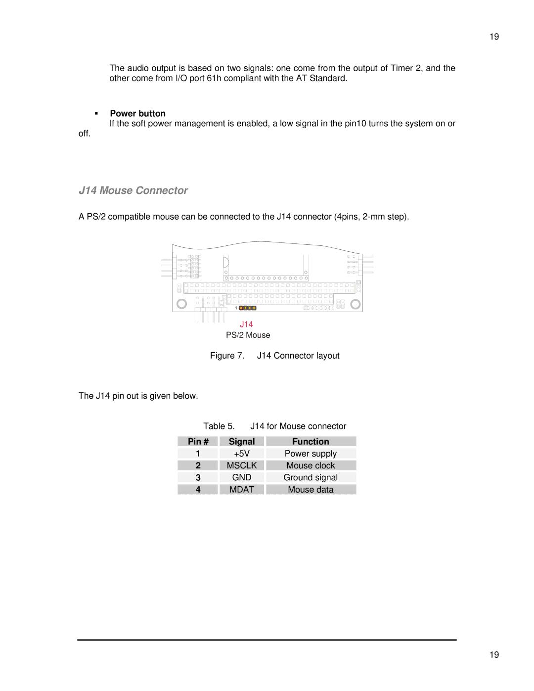
A PS/2 compatible mouse can be connected to the J14 connector (4pins,
J14
PS/2 Mouse
Figure 7. J14 Connector layout
The J14 pin out is given below.
Table 5. J14 for Mouse connector
Pin # | Signal | Function |
1 | +5V | Power supply |
2 | MSCLK | Mouse clock |
3 | GND | Ground signal |
4 | MDAT | Mouse data |
19