10,12,14,16, 18..25 GND GND 18..25 18,20,22,24
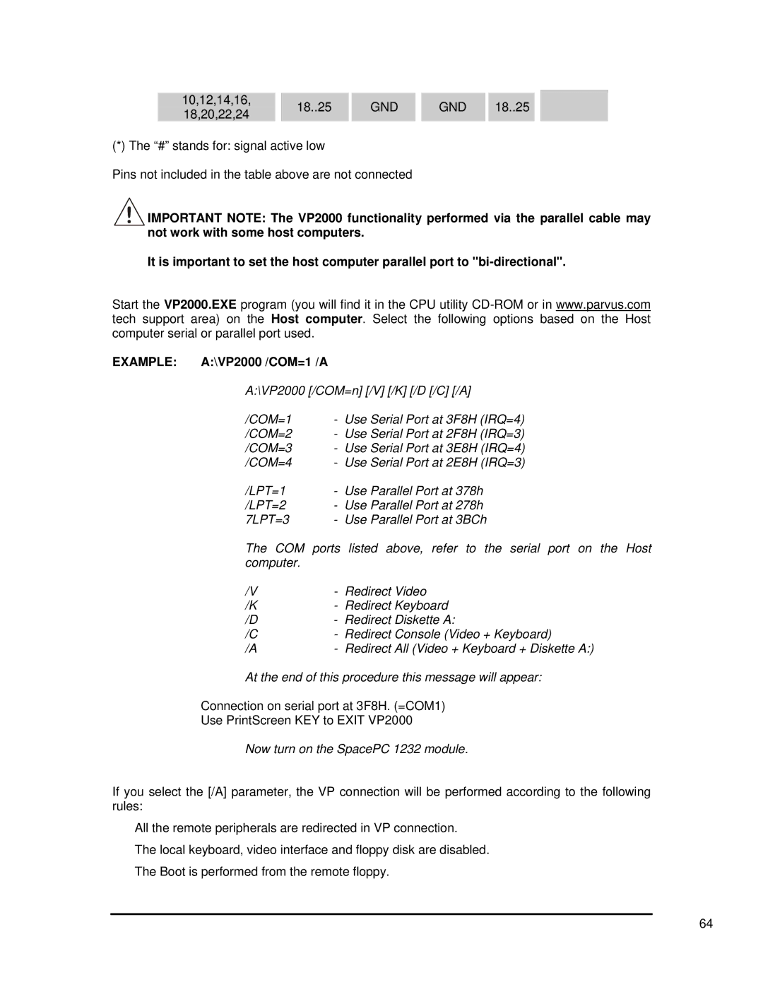
(*) The “#” stands for: signal active low
Pins not included in the table above are not connected
![]()
![]()
![]() IMPORTANT NOTE: The VP2000 functionality performed via the parallel cable may not work with some host computers.
IMPORTANT NOTE: The VP2000 functionality performed via the parallel cable may not work with some host computers.
It is important to set the host computer parallel port to
Start the VP2000.EXE program (you will find it in the CPU utility
EXAMPLE: A:\VP2000 /COM=1 /A
A:\VP2000 [/COM=n] [/V] [/K] [/D [/C] [/A]
/COM=1 | - Use Serial Port at 3F8H (IRQ=4) | |
/COM=2 | - Use Serial Port at 2F8H (IRQ=3) | |
/COM=3 | - Use Serial Port at 3E8H (IRQ=4) | |
/COM=4 | - Use Serial Port at 2E8H (IRQ=3) | |
/LPT=1 | - | Use Parallel Port at 378h |
/LPT=2 | - | Use Parallel Port at 278h |
7LPT=3 | - Use Parallel Port at 3BCh | |
The COM ports listed above, refer to the serial port on the Host computer.
/V | - | Redirect Video |
/K | - | Redirect Keyboard |
/D | - | Redirect Diskette A: |
/C | - | Redirect Console (Video + Keyboard) |
/A | - | Redirect All (Video + Keyboard + Diskette A:) |
At the end of this procedure this message will appear:
Connection on serial port at 3F8H. (=COM1)
Use PrintScreen KEY to EXIT VP2000…
Now turn on the SpacePC 1232 module.
If you select the [/A] parameter, the VP connection will be performed according to the following rules:
¾All the remote peripherals are redirected in VP connection.
¾The local keyboard, video interface and floppy disk are disabled.
¾The Boot is performed from the remote floppy.
64
