33
ATX Power Supply
¾Connect pin 1 and pin 7 to the ground signal of the ATX Power Supply Unit.
¾Connect pin 2 and pin 8 to the +5VDC source on the ATX Power Supply Unit.
¾Connect pin 4 to the +12VDC and pin 6 to the
¾Connect pin 11 to the +5VSB source on the ATX Power Supply Unit. This signal is always high, even if the power supply is turned off.
¾Connect pin 12 to the ATX ON signal of the ATX Power Supply Unit. This signal is used to power on the Power Supply itself.
Power button
If the soft power management is enabled, a low signal in this pin turns the system on or off.
![]() Note. The +12VDC and
Note. The +12VDC and
WARNING! IMPROPER CONNECTION OF THE POWER SUPPLY WILL RESULT IN SERIOUS DAMAGE FOR THE MODULE.
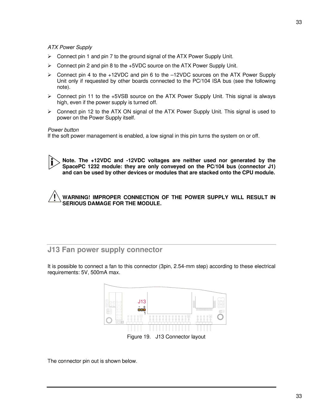
J13 Fan power supply connector
It is possible to connect a fan to this connector (3pin,
J13 |
- + |
Figure 19. J13 Connector layout
The connector pin out is shown below.
33