J11 Auxiliary Power Connector
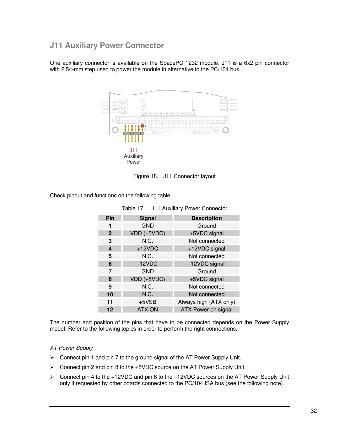
One auxiliary connector is available on the SpacePC 1232 module. J11 is a 6x2 pin connector with
J11
Auxiliary
Power
Figure 18. J11 Connector layout
Check pinout and functions on the following table.
Table 17. J11 Auxiliary Power Connector
Pin | Signal |
1 | GND |
2 | VDD (+5VDC) |
3 | N.C. |
4 | +12VDC |
5 | N.C. |
6 |
|
7 | GND |
8 | VDD (+5VDC) |
9 | N.C. |
10 | N.C. |
11 | +5VSB |
12 | ATX ON |
Description
Ground
+5VDC signal
Not connected
+12VDC signal
Not connected
Ground
+5VDC signal
Not connected
Not connected
Always high (ATX only)
ATX Power on signal
The number and position of the pins that have to be connected depends on the Power Supply model. Refer to the following topics in order to perform the right connections.
AT Power Supply
¾Connect pin 1 and pin 7 to the ground signal of the AT Power Supply Unit.
¾Connect pin 2 and pin 8 to the +5VDC source on the AT Power Supply Unit.
¾Connect pin 4 to the +12VDC and pin 6 to the
32