|
|
|
|
| ||||||
3.3 | Connection |
|
|
| ||||||
|
|
|
|
|
|
|
|
| ||
|
|
|
|
|
|
|
|
| ||
3.3.1 | Power Connection |
|
|
|
|
|
|
|
|
|
| The | |||||||||
| The power connection is made via a standard IEC mains cord to an | |||||||||
3.3.2 | rear panel and a latching power switch is provided on the front panel of the unit. |
|
|
| ||||||
Audio Connection |
|
|
|
|
|
|
|
|
| |
| Generally, each m odule will have an i nput connector (normally a female XLR) and an o utput connector | |||||||||
| (normally a male XLR). Depending upon the type of module other connectors, such as key inputs, may be | |||||||||
| present also. Connect the module inputs to the insert sends of your console or to your workstation outputs. | |||||||||
| Connect the module outputs to the corresponding insert returns or to your workstation inputs. | |||||||||
| Once the unit is connected switch it on , then route a signal to each channel in turn and check that it is | |||||||||
| returned to the correct input on your console or workstation. |
|
|
|
|
|
|
| ||
| Some module input and output gains can be set to operate at a nominal level of +4dBu or | |||||||||
| switch on the connector panel. Select the appropriate level for the equipment you are connecting to. If in | |||||||||
3.3.3 | doubt either refer to the section of this manual specific to the particular module or experiment! | |||||||||
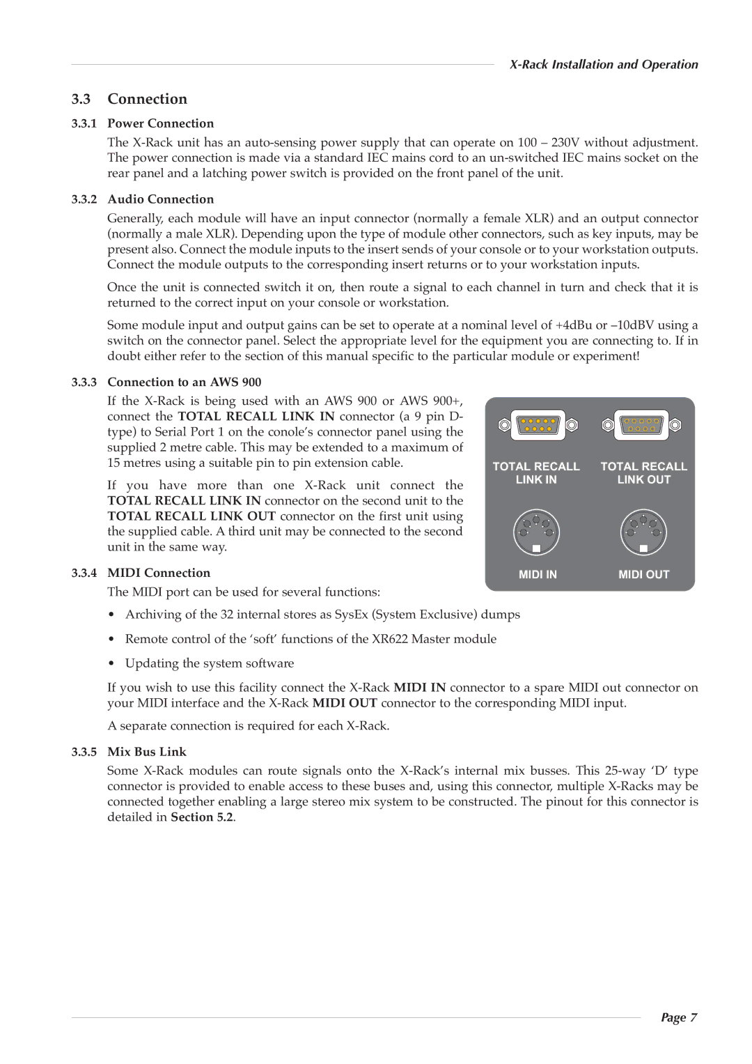
Connection to an AWS 900 |
| AWS 900+, |
|
|
|
|
|
|
| |
| If th e X |
|
|
|
|
|
|
| ||
| connect the TOTAL RECALL LINK IN | connector (a 9 pin D- |
|
|
|
|
|
|
| |
| type) to Serial Port 1 on the conole’s connector panel using the |
|
|
|
|
|
|
| ||
| supplied 2 metre cable. This may be extended to a maximum of | TOTAL RECALL | TOTAL RECALL | |||||||
| 15 metres using a suitable pin to pin extension cable. | |||||||||
| If you hav e more th an o ne | uni t co | nnect t he |
| LINK IN | LINK OUT | ||||
| TOTAL RECALL LINK IN connector on the second unit to the |
|
|
|
|
|
|
| ||
| TOTAL RECALL LINK OUT connector on the fir st unit using |
|
|
|
|
|
|
| ||
| the supplied cable. A third unit may be connected to the second |
|
|
|
|
|
|
| ||
| unit in the same way. |
|
|
|
|
|
|
|
|
|
|
|
|
|
|
|
|
|
|
| |
3.3.4 | MIDI Connection |
|
|
| MIDI IN | MIDI OUT | ||||
| The MIDI port can be used for several functions: |
|
|
|
|
|
|
|
| |
| • Archiving of the 32 internal stores as SysEx (System Exclusive) dumps |
|
|
| ||||||
| • Remote control of the ‘soft’ functions of the XR622 Master module |
|
|
| ||||||
| • Updating the system software |
|
|
|
|
|
|
|
|
|
If you wish to use this facility connect the
A separate connection is required for each
3.3.5Mix Bus Link
Some
Page 7