|
|
| |
D.4.3 Compressor Threshold |
|
| |
|
|
| |
|
|
| |
Adjustment: | 1. | Connect the level meter to the Output and set the oscillator level for | |
|
| ||
| 2. | Measure the DC voltage at test point TP14 relative to 0VA and adjust VR9 | |
|
| (COMP_THOLD) for 0V ±10mV. | |
D.4.4 Compressor Law |
|
|
|
Adjustment: | 1. | Set the oscillator level for +20dBu. | |
| 2. | Connect the level meter to the Output. Check for +20dBu ±0.5dB. | |
| 3. | Set the compressor ratio control fully clockwise and press in the | |
|
| compressor FST ATT and PK switches. | |
| 4. | Adjust VR10 (COMP_LAW) for a level of 14dBu ±0.1dB. | |
| 5. | Reset the compressor ratio control fully | |
D.4.5 Gate Threshold |
|
|
|
Adjustment: | 1. | Set the oscillator level for +10dBu and connect the level meter to the | |
|
| Output. | |
| 2. | Set the gate/expander to ‘gate’ by releasing the EXP switch, set the gate | |
|
| range and gate threshold controls fully clockwise. | |
| 3. | Adjust VR8 (GATE_THOLD) so that the gate just switches on. | |
| 4. | Check this adjustment by changing the oscillator level a little. | |
|
| VR8 if necessary so that the gate just opens when a +10dBu signal @ 1kHz | |
|
| is applied. | |
D.4.6 Output Balance |
|
|
|
Equipment Required: |
| Calibrated audio oscillator, audio level meter and a ‘balance’ adaptor (see | |
|
| below). | |
Test Signal: |
| 1kHz sine wave at +24dBu. | |
Input and Output: |
| Oscillator to the Input of the channel being tested, Output to the level | |
|
| meter via the ‘balance’ adaptor. | |
Unit Setup: |
| Ensure that all front panel switches are off and all controls are set fully | |
|
| ||
Adjustment: |
| Connect the test equipment to the each channel in turn and adjust VR13 | |
|
| (BAL) for minimum level (< 55dBr). | |
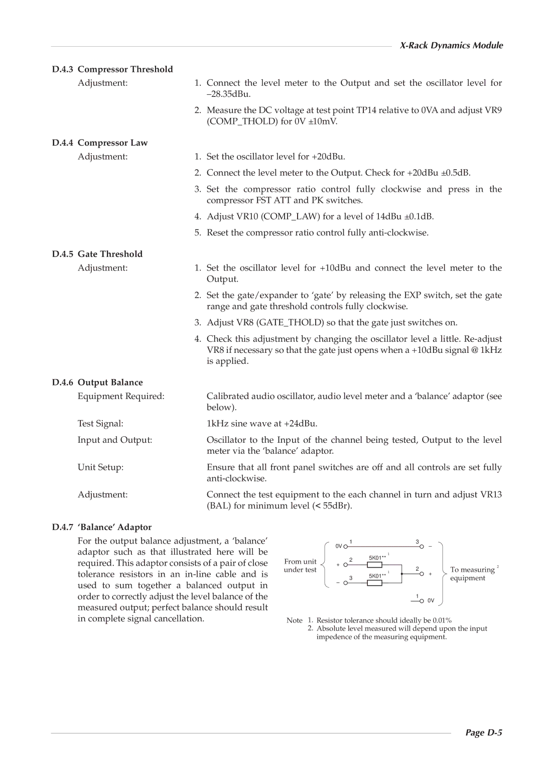
D.4.7 ‘Balance’ Adaptor
For the output balance adjustment, a ‘balance’ adaptor such as that illustrated here will be required. This adaptor consists of a pair of close tolerance resistors in an
| 1 |
| 3 | – |
|
| 0V |
|
|
| |
|
| 1 |
|
|
|
From unit | 2 | 5K01** |
|
|
|
+ |
|
|
| To measuring 2 | |
under test |
| 1 | 2 | + | |
| 3 | 5K01** |
| equipment | |
|
|
|
–
1 ![]() 0V
0V
Note 1. Resistor tolerance should ideally be 0.01%
2.Absolute level measured will depend upon the input impedence of the measuring equipment.