X-Rack Dynamics Module
D. The Dynamics Module
D.1 Connection
SYV |
Nu |
The module input and output gains can be set to operate at a nominal level of either +4dBu or
To check the input and output gains, set the compressor Ratio and Threshold controls fully clockwise and send a signal close to the nominal operating level of your mixer or DAW to the dynamics module. The lower three LEDs of the compression meter should light if the input level matches the selected operating level. Release the switch for +4dBu operation: push it in for
D.2 | Operation |
|
|
|
|
|
|
|
|
|
|
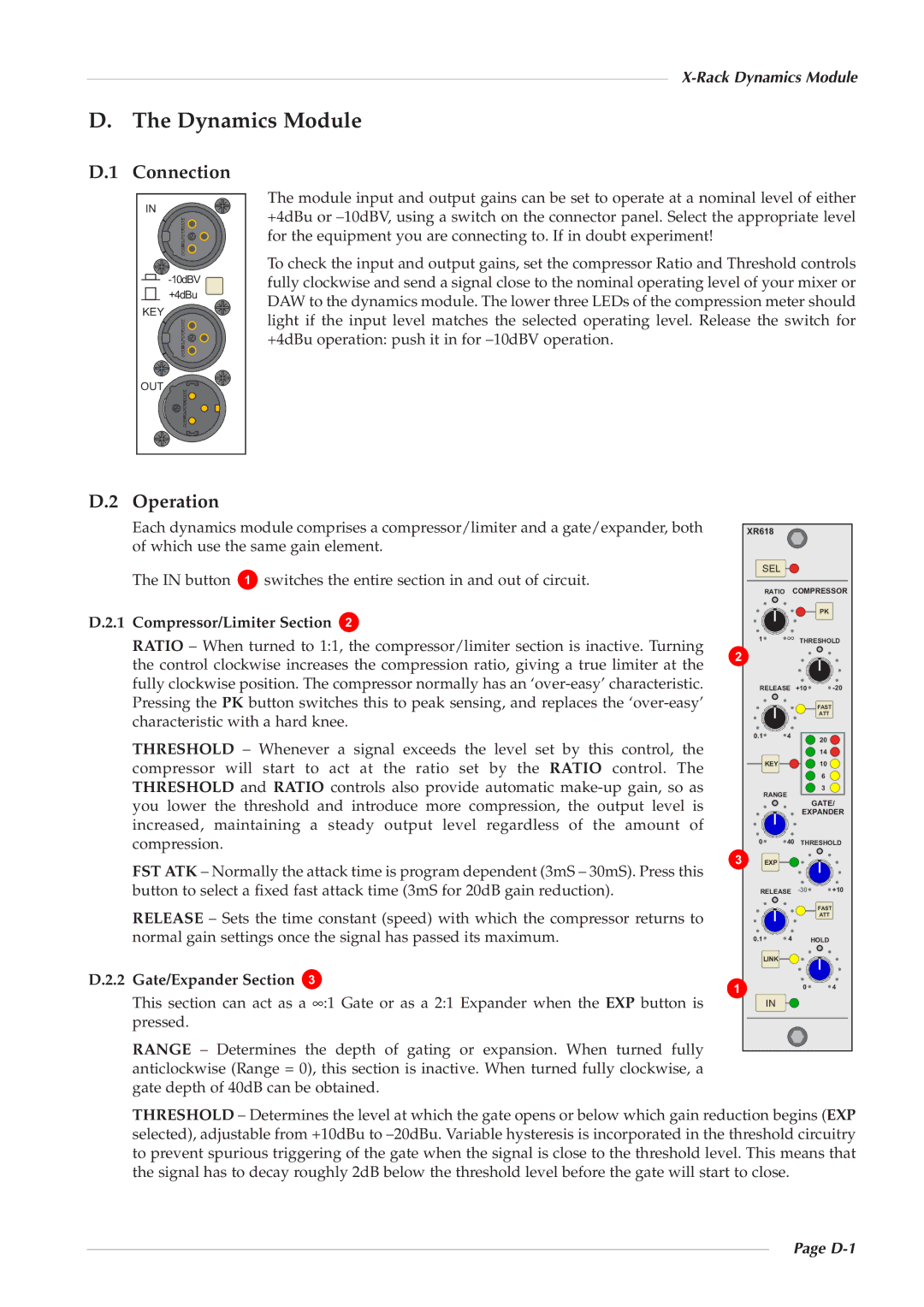
| Each dynamics module comprises a compressor/limiter and a gate/expander, both | XR618 |
|
| |||||||
| of which use the same gain element. |
|
|
|
|
| |||||
| The IN button | G | switches the entire section in and out of circuit. |
|
|
| |||||
D.2.1 | Compressor/Limiter Section | H |
|
|
|
| ∞ |
| |||
| RATIO – When turned to 1:1, the compressor/limiter section is inactive. Turning | G |
| ||||||||
| H |
|
| ||||||||
| the control clockwise increases the compression ratio, giving a true limiter at the |
|
| ||||||||
|
|
|
| ||||||||
| fully clockwise position. The compressor normally has an |
| 8GF | CHF | |||||||
| Pressing the PK button switches this to peak sensing, and replaces the |
|
|
| |||||||
| characteristic with a hard knee. |
|
|
|
|
|
| ||||
|
|
|
|
|
|
|
|
| FDG | K | HF |
| THRESHOLD – | Whenever | a | signal exceeds | the | level set by this control, the |
|
| |||
|
|
| GK | ||||||||
| compressor will | start | to act | at the ratio | set | by the RATIO control. The |
|
| GF | ||
|
|
| M | ||||||||
| THRESHOLD and RATIO controls also provide automatic |
|
| ||||||||
|
|
| I | ||||||||
| you lower the threshold and introduce more compression, the output level is |
|
|
| |||||||
| increased, maintaining a steady output level regardless of the amount of |
|
|
| |||||||
| compression. |
|
|
|
|
|
|
| F | KF |
|
|
|
|
|
|
|
|
|
|
| ||
| FST ATK – Normally the attack time is program dependent (3mS – 30mS). Press this | I |
|
| |||||||
|
|
|
| ||||||||
| button to select a fixed fast attack time (3mS for 20dB gain reduction). |
| CIF | 8GF | |||||||
|
|
|
|
|
|
|
|
|
| ||
| RELEASE – Sets the time constant (speed) with which the compressor returns to |
|
|
| |||||||
| normal gain settings once the signal has passed its maximum. | FDG | K |
| |||||||
D.2.2 | Gate/Expander Section | I |
|
|
|
| G | F | K | ||
|
|
|
|
|
|
|
|
| |||
|
|
|
|
|
|
|
|
|
| ||
| This section can act as a ∞ :1 Gate or as a 2:1 Expander when the EXP button is |
|
|
| |||||||
| pressed. |
|
|
|
|
|
|
|
|
|
|
| RANGE – Determines the depth of gating or expansion. When turned fully |
|
|
| |||||||
| anticlockwise (Range = 0), this section is inactive. When turned fully clockwise, a |
|
|
| |||||||
| gate depth of 40dB can be obtained. |
|
|
|
|
| |||||
THRESHOLD – Determines the level at which the gate opens or below which gain reduction begins (EXP selected), adjustable from +10dBu to