X-Rack Installation and Operation
When Remote Mode is set to MIDI (‘m1’), the ‘soft’ controls on the XR622 Master module may be remotely operated as MIDI controls. The Master module controls will continue to function until a valid MIDI packet has been received, after which all of the ‘soft’ controls will be locked out – operating these controls under these conditions will result in an ‘re’ message on the
Note. | Setting Remote Mode to MIDI will disable the AWS 900 Total Recall connection. |
| ||
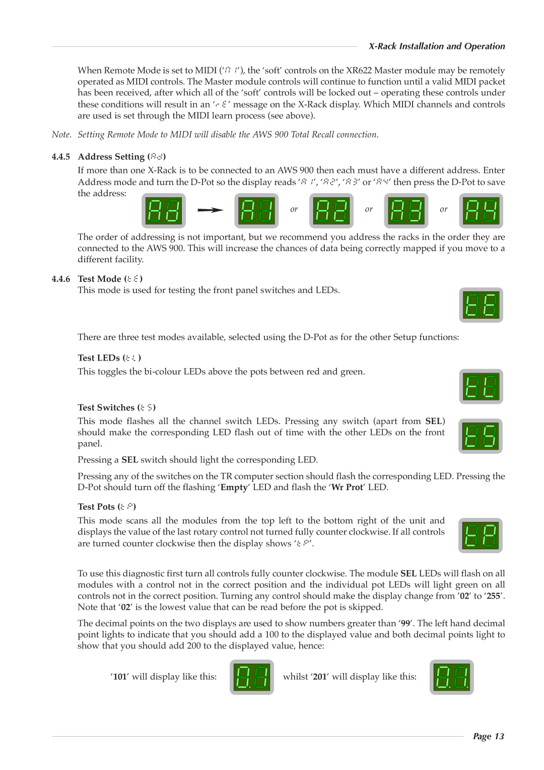
4.4.5 | Address Setting (ad) |
|
|
|
| If more than one | |||
| Address mode and turn the | |||
| the address: | or | or | or |
|
| |||
The order of addressing is not important, but we recommend you address the racks in the order they are connected to the AWS 900. This will increase the chances of data being correctly mapped if you move to a different facility.
4.4.6Test Mode (te)
This mode is used for testing the front panel switches and LEDs.
There are three test modes available, selected using the
Test LEDs (tl)
This toggles the
Test Switches (t5) This m ode flashes all th e chan nel switch LEDs. Pressin g any switc h (apart from SEL)
should make the cor responding LED flash out of time with the other LEDs on the front panel.
Pressing a SEL switch should light the corresponding LED.
Pressing any of the switches on the TR computer section should flash the corresponding LED. Pressing the
Test Pots (tp)
This mo de scans all t he modules from the top left to the bottom right o f the unit and
displays the value of the last rotary control not turned fully counter clockwise. If all controls are turned counter clockwise then the display shows ‘tp’.
To use this diagnostic first turn all controls fully counter clockwise. The module SEL LEDs will flash on all modules with a c ontrol not in the correct position and the individual pot LEDs will ligh t green on all controls not in the correct position. Turning any control should make the display change from ’02’ to ‘255’. Note that ‘02’ is the lowest value that can be read before the pot is skipped.
The decimal points on the two displays are used to show numbers greater than ‘99’. The left hand decimal point lights to indicate that you should add a 100 to the displayed value and both decimal points light to show that you should add 200 to the displayed value, hence:
‘101’ will display like this: | whilst ‘201’ will display like this: |
Page 13