LMF Band controls: |
|
Frequency | Variable from 200Hz to 2.5kHz |
Gain | Variable by > ±20dB |
‘Q’ | Variable from 0.5 to 2.5 (may also vary with gain) |
LF Band controls: |
|
Frequency | Variable from 40Hz to 600Hz |
Gain | Variable between ±16.5dB |
‘Q’ | 2.5 (on ‘ ’ setting) |
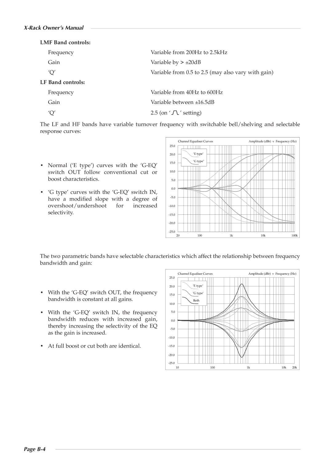
The LF and HF bands have variable turnover frequency with switchable bell/shelving and selectable response curves:
•Normal (‘E type’) curves with the
•‘G type’ curves with the
Channel Equaliser Curves | Amplitude (dBr) v Frequency (Hz) |
25.0
20.0’E type’
15.0 | ’G type" |
|
10.0
5.0
0.0
20 | 100 | 1k | 10k | 100k |
The two parametric bands have selectable characteristics which affect the relationship between frequency bandwidth and gain:
•With the
•With the
•At full boost or cut both are identical.
Channel Equaliser Curves | Amplitude (dBr) v Frequency (Hz) |
25.0 |
|
|
|
|
20.0 | ’E type’ |
|
|
|
15.0 | ’G type’ |
|
|
|
|
|
|
| |
10.0 | Both |
|
|
|
|
|
|
| |
5.0 |
|
|
|
|
0.0 |
|
|
|
|
|
|
|
| |
|
|
|
| |
|
|
|
| |
|
|
|
| |
|
|
|
| |
10 | 100 | 1k | 10k | 20k |