5.Miscellaneous
X-Rack Installation and Operation
5.1 X-Rack Internal Links and Fuses
5.1.1 Fuses (Mains Inlet)
The power s upply module is internally fused. In th e event of this fuse failing the entire unit s hould be returned to your nearest SSL Service agent.
5.1.2 Internal Fuses
The in ternal power rail fu ses w ill automatically res et once t he fault conditio n has been removed and should not need to be replaced.
5.1.3 Links
There are no user settable links.
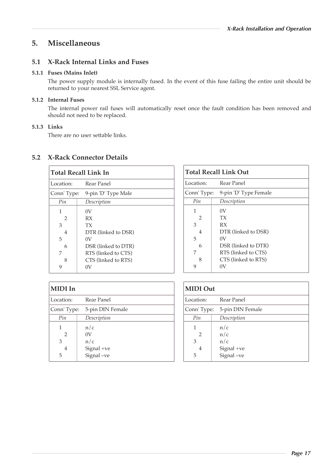
5.2X-Rack Connector Details
Total Recall Link In | Total Recall Link Out |
Location: | Rear Panel |
Conn' Type: | |
Pin | Description |
1 | 0V |
2 | RX |
3 | TX |
4 | DTR (linked to DSR) |
5 | 0V |
6 | DSR (linked to DTR) |
7RTS (linked to CTS)
8 CTS (linked to RTS)
9 0V
MIDI In
Location: | Rear Panel |
Conn' Type: | |
Pin | Description |
1 | n/c |
2 | 0V |
3 | n/c |
4 | Signal +ve |
5 | Signal |
Location: | Rear Panel |
Conn' Type: | |
Pin | Description |
1 | 0V |
2 | TX |
3 | RX |
4 | DTR (linked to DSR) |
5 | 0V |
6 | DSR (linked to DTR) |
7RTS (linked to CTS)
8 CTS (linked to RTS)
9 0V
MIDI Out
Location: | Rear Panel |
Conn' Type: | |
Pin | Description |
1 | n/c |
2 | n/c |
3 | n/c |
4 | Signal +ve |
5 | Signal |
Page 17