March
SDX-800V SDX-800V/R 5.25Model
Sony Business Europe Electronics Devices Marketing Singapore
ESD EMC
Changing List
This page intentionally left blank
Introduction
Specifications
Installation Guide
Installation
Operation
Summary of LED Indications Operator Action
Scsi Interface
Command Specification
Mode Sense 6/10 1Ah and 5Ah
Mode Select 6/10 15h and 55h
Space 11h
Test Unit Ready 00h
Appendix G Disaster Recover
Drive Diagnostics
Appendix F AIT based Worm system
Appendix H Glossary
14.6 Reset Handling
Features of the Drive
About this Product Specification Manual
Introducing the Sony AIT Technology
Introduction
Reference
How to get ECMA-222, 246, 291, 292, 329 Standard Document
This page intentionally left blank
Dimensions SDX-800V
Specifications Dimensions
2a SDX-800V Mounting Holes
Mounting Holes
2b SDX-800V/R Mounting Holes
Connectors
Weight
Environmental Specifications
Temperature and Humidity Range
Suspended Particulate
Altitude
Vibration
Shock
Data Capacity
Performance Specification
Initialize Time
Data transfer Rate
Sustained Data Transfer Rate to and from the Tape
Burst Transfer Rate to and from the Scsi Bus
Load Time
Error Rate
Unload Time
Search Time
Definition of Failure
Retry Limits on Rewrites
Mean Time Between Failures
Mean Time to Repair
Installation Requirements
Safety
Conditions of Acceptability
TUV
Data Compression
Power Requirements
Voltage Max Ripple Current Typical Maximum
This page intentionally left blank
DIP switch & Connector
Installation Guide
DIP SW Mode
Termination Power Switch
Scsi ID Number Jumper
Scsi ID3 ID2 ID1 ID0
Data Compression on Switch
Parity Disable Jumper
Power Connector
Scsi 68 pin Connector
+ATN
Ground Diffsens Termpwr Reserved
Ground BSY +BSY ACK +ACK
+RST
Ground Termpwr Reserved
Ground
Ground BSY ACK
MSG Ground SEL REQ
Attaching the Dust Cover
Attaching and Removing the Dust Cover
Removing the Dust Cover
This page intentionally left blank
Summary of LED Indications
Tape Motion Cleaning Request Replace Tape
Meaning of each LED indications
LED
Hard Reset Hole
Operator Action Powering up the SDX-800V
Inserting Cassettes
Removing Cassettes
Internal Function
Power-Fail or Scsi Reset Handling
Diagnostic Status Display
Diagnostic and Normal Status Displays
Normal Status Display
Front Panel Test
Tape Format
Tape Alert
Normal LED indications
Troubleshooting Guide
Maintenance, Troubleshooting and Service Head Cleaning
Tape is in the drive and will not eject
Photo 2 The Initial Position of the Threading Mechanism
Tape guide surface Cartridge Detail a
Read/Write Problems
Clearance for Service
Packaging for Return to Sony
Replace Tape
This page intentionally left blank
Supported Messages
Overview of the Scsi Interface
Supported Scsi Commands Command Name Operation Code
Supported Commands
Disconnect
Scsi Bus Operation Typical Scsi Operation
Message Descriptions Code Direction
Message Specification
Identify
Extended Message 01h
Command Complete 00h
Parallel Protocol Request 04h
Synchronous Data Transfer Request
Synchronous Data Transfer Request 01h
Byte Value Description
Responding Device Sdtr response Implied Agreement
Synchronous Data Transfer Rates
Byte Value
Wide Data Transfer Request
Save Data Pointer 02h
Restore Pointers 03h
Disconnect 04h
Message Parity Error 09h
Initiator Detected Error 05h
Abort 06h
Message Reject 07h
Identify 80h-FFh
BUS Device Reset 0Ch
Ignore Wide Residue 23h
Ignore Wide Residue Message Byte Value
Status Specification
Scsi Interface
This page intentionally left blank
Para Scsi Command OP Code
Scsi Commands and Page Index
Load /UNLOAD
Erase 19h
Bit Byte Operation Code 12h Obsolete Reserved CmdDT
Inquiry 12h
Evpd
Or Operation Code Reserved Allocation Length Control
MSB
Bit Byte
Sony LSB MSB
LSB MSB
Length 0Ah Product Serial number in Ascii
Vital Product Data
Identifier length 08h Ieee EUI-64 Code
Length 32h Reserved 00h Code set 02h Identifier type 01h
CDB size m-5 CDB usage data
Immed
LOAD/UNLOAD 1Bh
Hold
Reten Load
Hold Reten Load Action
Load Unload Command Parameter Combinations
MSB
Locate 2Bh
LSB
Obsolete Reserved
LOG Select 4Ch
PCR
Parameter List Length
Code Description
Codes
MIC Variable Length Information Parameter Codes Description
Obsolete Reserved PPC Code
LOG Sense 4Dh
Reserved Parameter Pointer
Control field values Value Type of Parameter Values
Supported Log Pages
Log Page Descriptor
TSD
Log Parameter Descriptor
Lbin
12 Threshold Met criteria
Supported Log Pages
TMC
Threshold Met Criteria
Summary List of Supported Pages
Write and Read Error Counters Pages
Last N Error Events List
Bit Byte Reserved Code 2Eh
Tape Alert Log
Length 140h
Parameter Code n 5n+1
Tape Alert Log Page Parameter Codes
LOG Sense
Restart the operation
That is not mechanically
21 Tape Log Bit Byte Reserved Code 30h
Tape Log Page Sony Unique
Length 98h
TMC Lbin Parameter Length m Parameter Value
Tape Capacity Log Page Sony Unique
Length 00 20h when AIT bit =0 04 00h when AIT bit =1
23 Tape Capacity Log Bit Byte Code 31h
TMC Lbin Parameter Length 04h
Drive Usage Log Page Sony Unique
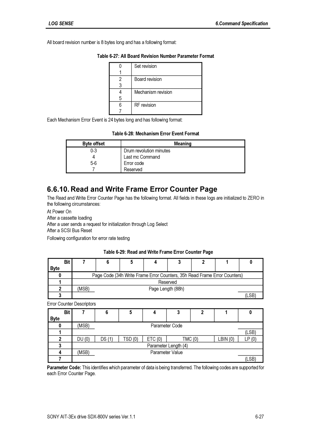
Read and Write Frame Error Counter
AIT1
32 Data Compression Transfer Log Bit Byte Reserved Code 39h
Data Compression Transfer Log Page Sony Unique
Length 58h
Parameter Code n
33 AIT Log Bit Byte Code 3Ch Reserved
AIT Log Page Sony Unique
Length n+1
TSD TMC Lbin Parameter
LOG Sense
34 MIC Fixed Length Information Bit Byte Code 3Dh Reserved
MIC Fixed Length Information Page Sony Unique
ABS
AIT
Prth Ponej
MSB Current Amount of Data Written LSB
29-31
24-27
42-99
Parameter Code 0017h Element Address
Important Note
MIC Variable Length Information Page Sony Unique
Length n-3
Parameter Code Description
Mode Select 6 CDB Format Bit Byte Operation
Mode SELECT6/10 15h and 55h
37 Sequential-Access Density Codes Code Value
38 Mode Select Page Header Bit Byte
Mode Fixed Bit in Read, Write Block Length
39 Supported Mode Select Page Codes Description
Code Additional Page Length
Dtdc
Disconnect-Reconnect Page 02h
Autoload Mode
Control Mode Page 0Ah
Autoload Mode field
Bit Byte Reserved Code 0Ah Length 0Ah
DCE
Data Compression Control Page 0Fh
DDE RED
42 Device Configuration Bit Byte
Device Configuration Page 10h
CAP
REW
Mode Select
IDP Psum
Medium Partitions Parameter Page 11h
Mode Select
Mrie MSB
Informational Exceptions Control Page 1Ch
AIT Device Configuration Page 31h
Bit Combination Table
47 Append Partition Bit Byte Reserved Code 32h Length
Append Partition 32h This mode page is not supported
Reserved Partition units
Partition Size Descriptor
Append Partition example procedure
Case
Delete Partition 33h This mode page is not supported
New tape layout
Case 5 with PRTH=0
49 Mode Sense 6 CDB Format
Mode Sense 6/10 1Ah and 5Ah
DBD
PCF
Length 08h
52 Supported Mode Sense Page Codes
Number of Blocks 00 00 00h
SDX-T3N
Mode Sense 31h AIT Device Configuration
MIC Cartridge
AIT DEV Ulpbot Prth Ponej ABS MIC
Persistent Reserve in 5Eh
Service Action
MSB Generation LSB
Reservation Key
Reservation descriptor
SCOPE-SPECIFIC Address
Scope Type
Name Description
58 Persistent Reservation Scope Codes
59 Persistent Reservation Type Codes
Persistent Reserve OUT 5Fh
Service Action Scope Type
Parameter List Length 18h
Address
Type Service Action SCOPE- Specific Reservation KEY
Obsolete Reserved Prevent Control
Prevent Allow Medium Removal 1Eh
Bit Byte Operation Code 08h Obsolete Reserved
Read 08h
Sili
Fixed
Read
First Attribute ID
Read Attribute 8Ch
Reserved Control
64 Read Attribute service action codes
Attribute Values service action
Code Name Description
Available Data n-3
Attribute List service action
Attribute
Attribute
Volume List service action
Partition List service action
First Volume Number Number of Volumes Available
Available Data 2h
Obsolete Reserved Control
Read Block Limits 05h
69 Read Block Limits Data Bit Byte Reserved
Maximum Block Length Limit 80 00 00h
Read Buffer 3Ch
Buffer Capacity
72 Read Buffer Descriptor Bit Byte Reserved
Buffer ID The supported values are Description Offset
MSB Buffer Capacity LSB
Tclp Long
Read Position 34h
BOP EOP
BPU
MPU BPU
76 Read Position Data Format, long form Bit Byte
Block Number
File Number
Length 00 02h
Receive Diagnostic Results 1Ch
Supported Page Code 00h Supported Page Code 81h
Length 00 05h
Re-Sync Error Code Result a Result B Test Number
Parameter List Length Control
Release Unit 6/10 17h and 57h
MSB
Media
Report Density Support 44h
MSB Capacity LSB
104
103
105
106
167 168
166
171 172
179
319
317
320
321
Report Device Identifier A3h
Bit Byte Operation Code A3h Reserved Service Action
Reserved Allocation Length Control
86 LUN reporting parameter list format Bit Byte
Report Luns A0h
LUN List Length 00 00 08h
LUN List
Obsolete Reserved Allocation Length 1Ch Control
Request Sense 03h
Sksv
EOM ILI
CLN
MEW
BPV
SKSV1
SKSV0
90 Sense Key Descriptions
Recovered Error
Bytes Description Key
Cleaning Failure
Append Position Error
Cartridge Fault
END-OF-PARTITION / Medium Detected
Parameter Value Invalid
MIC Read Error
Saving Parameters not Supported
Not Ready to Ready TRANSITION, Medium MAY have Changed
Power ON, RESET, or BUS Device Reset Occurred
Medium Auxiliary Memory Accesible
Initiator Detected Error Message Received
Aborted Command
Command Phase Error
Volume Overflow
91 Reserve Unit 6 CDB format Bit Byte Operation
Reserve Unit 6/10 16h and 56h
MSB
Obsolete Reserved Immed Control
Rewind 01h
94 Diagnostic Page Format Bit Byte Code Reserved
Send Diagnostic 1Dh
Obsolete Reserved Self Test
UnitOfl
95 Diagnostic Test information
Reserved Parameter List Length Control
SET Device Identifier A4h
Obsolete Reserved Code
Space 11h
Count
98 Space codes
Sense Key
EOM
ASC/ASCQ
Check Condition
Not Ready
Test Unit Ready 00h
3A 00 Medium not Present
04 01 Logical Unit is Becoming Ready
Obsolete Reserve Fixed
Write 0Ah
Write Attribute 8Dh
Volume Number
Partition Number
MSB Parameter List Length LSB
LSB Attribute
104 Write Buffer Mode Field
103 Write Buffer Mode Field Description
Write Buffer 3Bh
Buffer ID Description Offset
Write Buffer
Bit Byte Operation Code 10h Obsolete Reserved WSmk Immed
Write Filemarks 10h
Number of File-marks or Set-marks
Power-on Self Test
Diagnostic Test
Overview
Send Diagnostic command Individual Test
Send Diagnostic command Self Test
Send Diagnostic Parameters SCSI-2 Bit Byte Code 81h Reserved
Diagnostic Test Number Summary
Sequence Test
Receive Diagnostic Result command
Mechanism Controller Kernel Test
Main Processor Kernel Test
Drive Diagnostics
Following list of error codes are supported by the drive
Diagnostics Results Reference
Error set 2 Diagnostic error
This page intentionally left blank
Alphabetic Order
ASC and Ascq Assignments
Byte Description
Message Error
Mechanical Positioning Error
Mode Parameters Changed
Logical Unit not Supported
Numeric Order
Appendix B ASC & Ascq Numeric Order
Command Sequence Error
Appendix C Scsi Commands Op Code Order
A3h 10-2 Sony AIT-3Ex drive SDX-800V series Ver.1.1
Byte
ASC and Ascq Assignments for AIT drive Sony Unique
11-2 Sony AIT-3Ex drive SDX-800V series Ver.1.1
Appendix E Medium Auxiliary Memory Attribute
Hold EOT Reten Load Control
Code 1Bh Reserved
Read
With Write
Attribute Type
MAM Attribute states
MAM Attribute Format Bit Byte
Format Name Description
MAM attribute formats
MAM attribute identifier range assignments
Attribute Identifiers Attribute Type Standardization
Device Common Attributes Attribute Name #Bytes Format
Vendor Identification
Device VENDOR/SERIAL Number attribute format Bit Byte
Product Serial Number
Current Amount of Data Written
Medium Usage History attribute format Bit
Appendix E
Change Partition Count
Current Write Reties Count
Partition Initialize Count
11 Medium Common Attributes Attribute Name #Bytes Format
Medium Type
12 Medium Type and Medium Type Information attributes
Medium Type Information
Standard host type attributes
14 Text Localisation Identifier
How to detect a Worm cartridge
Write-Protected WP Bit in Mode Sense Data
How to initialize a Worm cartridge
31h AIT Device Configuration Bit Byte
AIT=0
END
How to handle the Worm cartridge in the drive
13-4 Sony AIT-3Ex drive SDX-800 series Ver.1.1
Configuring The Drive For Disaster Recovery Operation
Creating Disaster Recovery Tape
Exiting DR Mode
Supported Cdrom DR Command Set Inquiry 12h
Reset Handling
Mode Sense/Select Page Code 0x3C
Read TOC
Appendix H Glossary
Appendix H
Appendix H
15-4 Sony AIT-3Ex drive SDX-800V series Ver.1.1