The terminals are designed for a cable
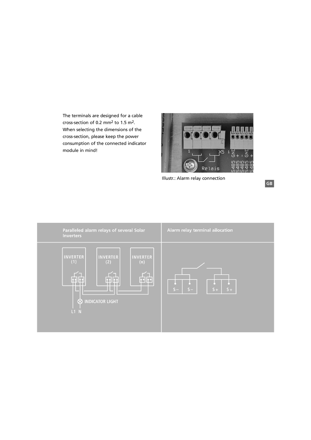
Illustr.: Alarm relay connection
GB
Paralleled alarm relays of several Solar Inverters
INVERTER | INVERTER | INVERTER |
(1) | (2) | (n) |
 INDICATOR LIGHT
L1 N
Alarm relay terminal allocation
S – | S – | S + | S + |