Manuals
/
SUPER MICRO Computer
/
Computer Equipment
/
Network Card
SUPER MICRO Computer
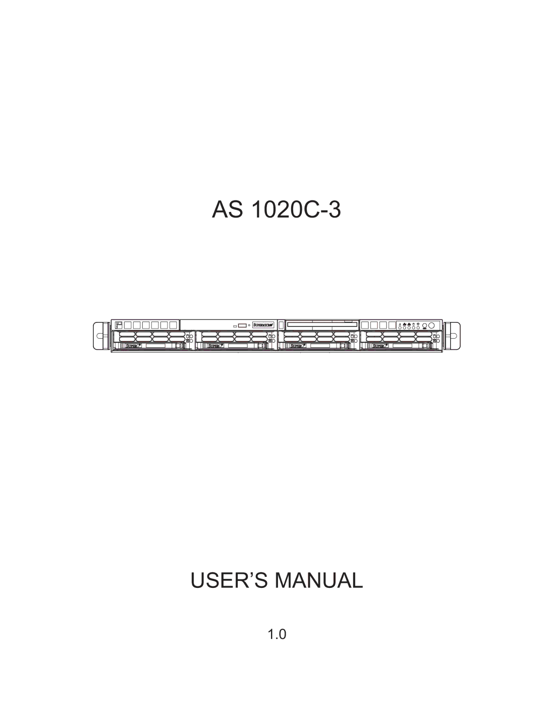
AS 1020C-3
user manual
Models:
AS 1020C-3
1
1
106
106
Download
106 pages
31.83 Kb
1
2
3
4
5
6
7
8
Install
Amibios Error Beep Codes
Alert Startup Delay
Onboard Indicators Description
Connecting Cables
Reset Button
Accessing the drive bays
Advanced Serverboard Setup
Connector Definitions
Bios
Page 1
Image 1
AS
1020C-3
USER’S MANUAL
1.0
Page 1
Page 2
Page 1
Image 1
Page 1
Page 2
Contents
AS 1020C-3
Manual Revision Release Date October 13
About This Manual
Preface
Manual Organization
Advanced Serverboard Setup
System Safety
Advanced Chassis Setup
Bios
Preface
Table of Contents
Advanced Serverboard Setup
System Safety
Pssmbus
Advanced Chassis Setup
Appendices
Bios
Page
Overview
Chapter Introduction
Processors
Serverboard Features
Memory
SAS Serial Attached Scsi
ATI Graphics Controller
Other Features
Onboard Controllers/Ports
System Power
Server Chassis Features
Serial Attached Scsi SAS Subsystem
Control Panel
Cooling System
NVidia nForce Pro 2200/AMD-8132 Chipset System Block Diagram
Headquarters
Contacting Supermicro
Europe
Asia-Pacific
Preparing for Setup
Chapter Server Installation
Unpacking the System
Rack Precautions
Choosing a Setup Location
Server Precautions
Rack Mounting Considerations
Installing the Rack Rails
Installing the System into a Rack
Identifying the Sections of the Rails
Identifying the Sections of the Rails
Installing the Chassis Rails
Installing the Server into a Rack
Installing the Server into the Rack
Installing the Server into a Telco Rack
Installing the Server into a Telco Rack
Checking the Serverboard Setup
Accessing the drive bays
Checking the Drive Bay Setup
CD-ROM and floppy disk drives
Check the SAS disk drives
Check the airflow
Supplying power to the system
Control Panel Buttons
Chapter System Interface
Control Panel LEDs
SAS Drive Carrier LEDs
Page
Electrical Safety Precautions
Chapter System Safety
General Safety Precautions
ESD Precautions
Installing the Onboard Battery
Operating Precautions
Precautions
Chapter Advanced Serverboard Setup
Handling the Serverboard
Unpacking
Mounting the Serverboard into a Chassis
Processor and Heatsink Installation
CPU Backplates
Is not recommended
Installing the Processor
Installing Heatsinks
Installing the Heatsinks
Connecting Data Cables
Connecting Cables
Connecting Power Cables
Front Control Panel Header Pins JF1
Connecting the Control Panel
I/O Ports
Installing Memory
Support
Maximum memory two CPUs
Optimizing memory performance
Adding PCI Cards
PCI card installation
PCI slots
H8DCR-3 Serverboard Layout
Serverboard Details
Connectors Description
Jumpers Description Default Setting
Onboard Indicators Description
H8DCR-3 Quick Reference
ATX Power Connector
Connector Definitions
Processor Power Connector
Auxiliary Power Connector
Overheat/Fan Fail LED
Power LED
Power Button
Reset Button
LAN1/2 Ethernet Ports
Universal Serial Bus Ports USB0/1
Serial Ports
Extra USB Headers
Fan Headers
Chassis Intrusion
ATX PS/2 Keyboard and PS/2 Mouse Ports
Power LED/Speaker
Overheat LED
Wake-On-LAN
Alarm Reset Header
Wake-On-Ring
SMBus Header
Compact Flash Power Connector
Power Fail Connector
I2C for SAS Connector
JSLED1 Header
Explanation Jumpers
Jumper Settings
Cmos Clear
I2C to PCI Enable/Disable
3rd Power Supply Fail Signal Enable/Disable
VGA Enable/Disable
Compact Flash Master/Slave
Onboard Speaker Enable/ Disable
Watch Dog Enable/Disable
SAS Controller Enable Disable
PCI-X Slot Frequency Select
LAN1/2 Enable/Disable
LAN1/LAN2 LEDs
Onboard Indicators
+3.3V Standby LED
SAS Activity LEDs
Floppy, IDE and SAS Connections
Floppy Connector
SAS Ports
IDE Connectors
Serial Attached Scsi SAS
Enabling SAS RAID
Enabling SAS RAID
Creating a RAID Array
SAS Controller Utility
Array Configuration Utility Screen
Selecting Drives for the Array
Additional Functions
10. Driver/Tool Installation Display Screen
Installing Drivers
Static-Sensitive Devices
Chapter Advanced Chassis Setup
Tools Required
Chassis Front and Rear Views
Control Panel
System Fans
Installing a new fan
System Fan Failure
Replacing System Cooling Fans
Removing the Front Bezel
Drive Bay Installation/Removal
Removing the Front Bezel
Accessing the Drive Bays
Mounting a SAS drive in a drive carrier
Serial Attached Scsi SAS Drive Installation
SAS Backplane
Installing/removing hot-swap SAS drives
CD-ROM and Floppy Drive Installation
Power Supply Failure
Power Supply
Removing/Replacing the Power Supply
Removing the power supply
Removing/Replacing the Power Supply
Chapter
Starting the Setup Utility
Introduction
Main Menu
Advanced Settings Menu
CPU Configuration
IDE Configuration
Primary/Secondary IDE Master/Slave
LBA/Large Mode
Type
Block Multi-Sector Transfer
First Boot Device From
DMA Mode
A.R.T
Bit Data Transfer
Configuration nVidia RAID ROM
PCI/PnP Menu
Floppy Configuration
NorthBridge Configuration
Advanced Chipset Control
ECC Configuration Dram ECC Enable
User Config Mode
Bank Interleaving
Burst Length
SouthBridge Configuration
Device Configuration
Hyper Transport Configuration
DMI Event Logging
AMD PowerNow Configuration
Console Redirection
Ipmi 1.5 Configuration
System Health Monitor
Startup Delay
Alert Startup Delay
Cbmc Watch Dog Timer Action
Set LAN Configuration IP Address
Bios Ehci Hand-Off
USB 2.0 Controller Mode
USB Configuration
USB Controller Support
Boot Settings Configuration
Boot Menu
OS Installation
Boot Device Priority
Security Menu
Removeable Drives
Exit Menu
Page
Amibios Error Beep Codes
Appendix a Bios Error Beep Codes
Beep Code Error Message Description
AS1020C-3 User’s Manual
Uncompressed Initialization Codes
Appendix B Bios Post Checkpoint Codes
Bootblock Recovery Codes
Uncompressed Initialization Codes
AS1020C-3 User’s Manual
Appendix B Bios Post Checkpoint Codes
AS1020C-3 User’s Manual
A9h Aah Abh B0h B1h 00h
AS1020C-3 User’s Manual
Appendix C System Specifications
Power Supply
Weight
Serverboard
Chassis
Regulatory Compliance
Top
Page
Image
Contents