Chapter 5: Advanced Serverboard Setup
Extra USB Headers
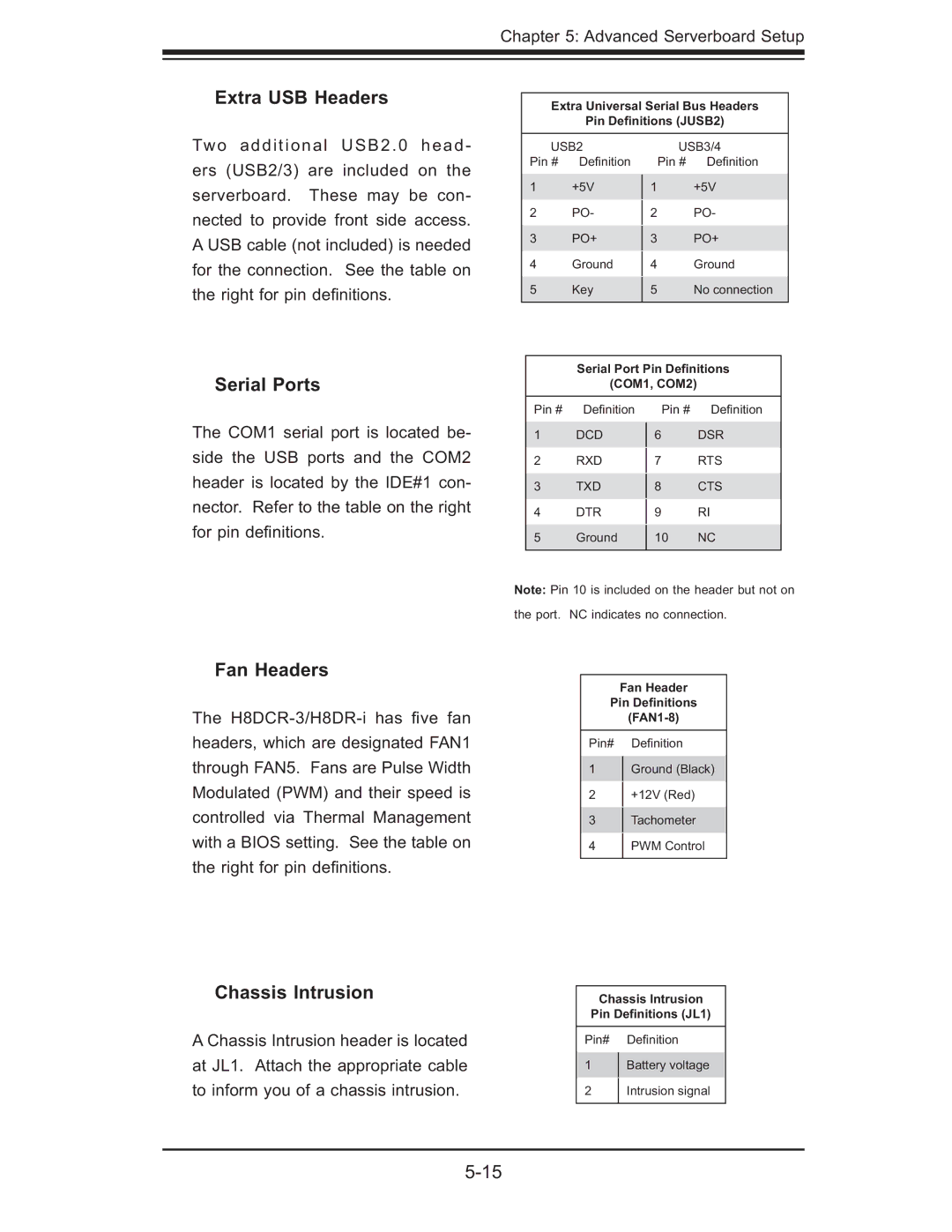
Extra Universal Serial Bus Headers
Pin Definitions (JUSB2)
Two additional USB2.0 head- ers (USB2/3) are included on the serverboard. These may be con- nected to provide front side access. A USB cable (not included) is needed for the connection. See the table on the right for pin defi nitions.
USB2
Pin # Defi nition
1+5V
2PO-
3PO+
4Ground
5Key
USB3/4
Pin # Defi nition
1+5V
2PO-
3PO+
4Ground
5No connection
Serial Ports
The COM1 serial port is located be- side the USB ports and the COM2 header is located by the IDE#1 con- nector. Refer to the table on the right for pin defi nitions.
Fan Headers
The
Chassis Intrusion
A Chassis Intrusion header is located at JL1. Attach the appropriate cable to inform you of a chassis intrusion.
Serial Port Pin Definitions
(COM1, COM2)
Pin # | Defi nition | Pin # | Defi nition |
1 | DCD | 6 | DSR |
2 | RXD |
| RTS |
7 | |||
3 | TXD |
| CTS |
8 | |||
4 | DTR |
| RI |
9 | |||
5 | Ground |
| NC |
10 | |||
|
|
|
|
Note: Pin 10 is included on the header but not on the port. NC indicates no connection.
Fan Header
Pin Definitions
Pin# Defi nition
1Ground (Black)
2 +12V (Red)
3Tachometer
4PWM Control
Chassis Intrusion
Pin Definitions (JL1)
Pin# Defi nition
1Battery voltage
2Intrusion signal