Power LED/Speaker
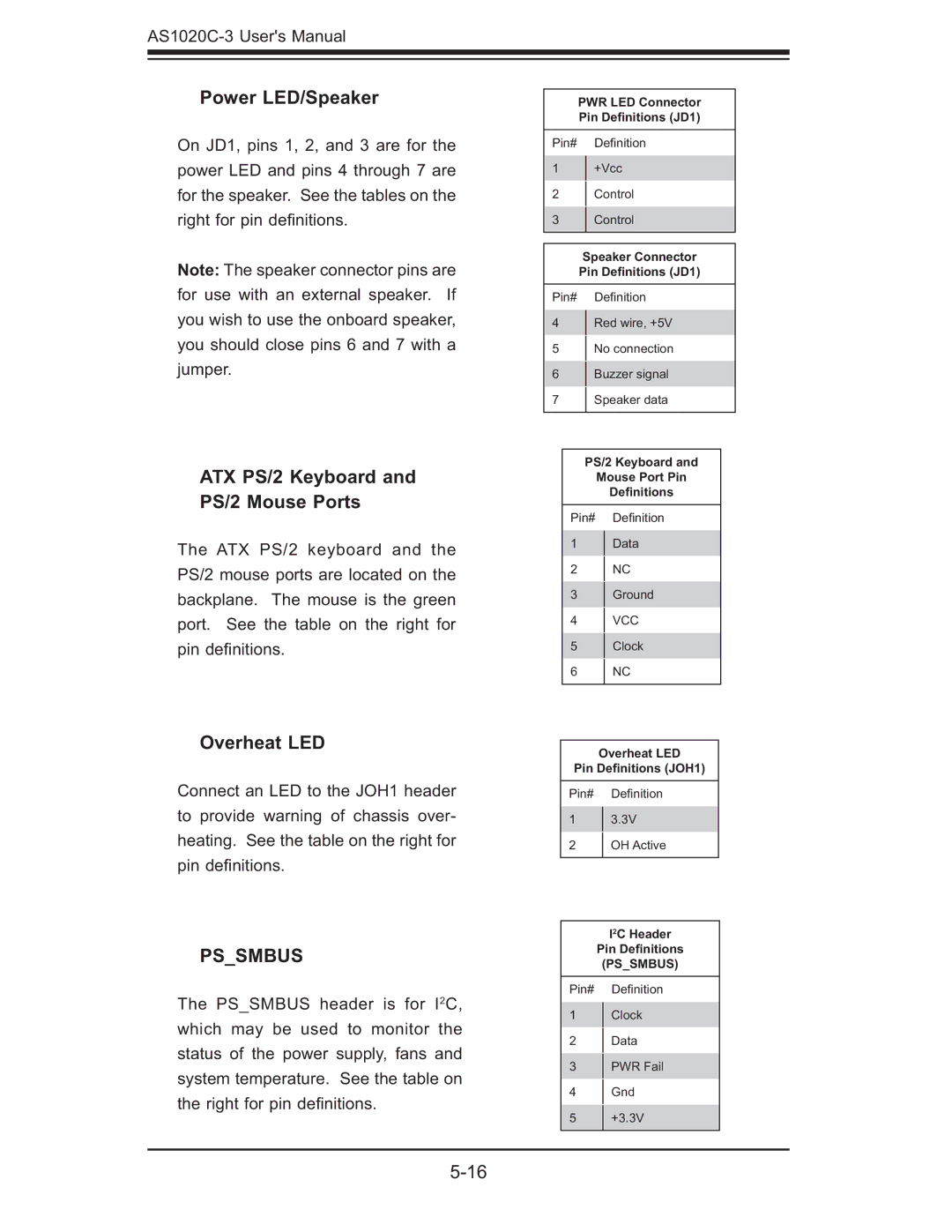
On JD1, pins 1, 2, and 3 are for the power LED and pins 4 through 7 are for the speaker. See the tables on the right for pin defi nitions.
Note: The speaker connector pins are for use with an external speaker. If you wish to use the onboard speaker, you should close pins 6 and 7 with a jumper.
ATX PS/2 Keyboard and PS/2 Mouse Ports
The ATX PS/2 keyboard and the PS/2 mouse ports are located on the backplane. The mouse is the green port. See the table on the right for pin defi nitions.
Overheat LED
Connect an LED to the JOH1 header to provide warning of chassis over- heating. See the table on the right for pin defi nitions.
PS_SMBUS
The PS_SMBUS header is for I2C, which may be used to monitor the status of the power supply, fans and system temperature. See the table on the right for pin defi nitions.
PWR LED Connector Pin Definitions (JD1)
Pin# Defi nition
1+Vcc
2Control
3Control
Speaker Connector Pin Definitions (JD1)
Pin# Defi nition
4Red wire, +5V
5 No connection
6Buzzer signal
7 Speaker data
PS/2 Keyboard and
Mouse Port Pin
Definitions
Pin# Defi nition
1Data
2NC
3Ground
4VCC
5Clock
6 NC
Overheat LED
Pin Definitions (JOH1)
Pin# Defi nition
13.3V
2OH Active
I2C Header
Pin Definitions
(PS_SMBUS)
Pin# Defi nition
1Clock
2Data
3PWR Fail
4Gnd
5 +3.3V
