5-9 Connector Definitions
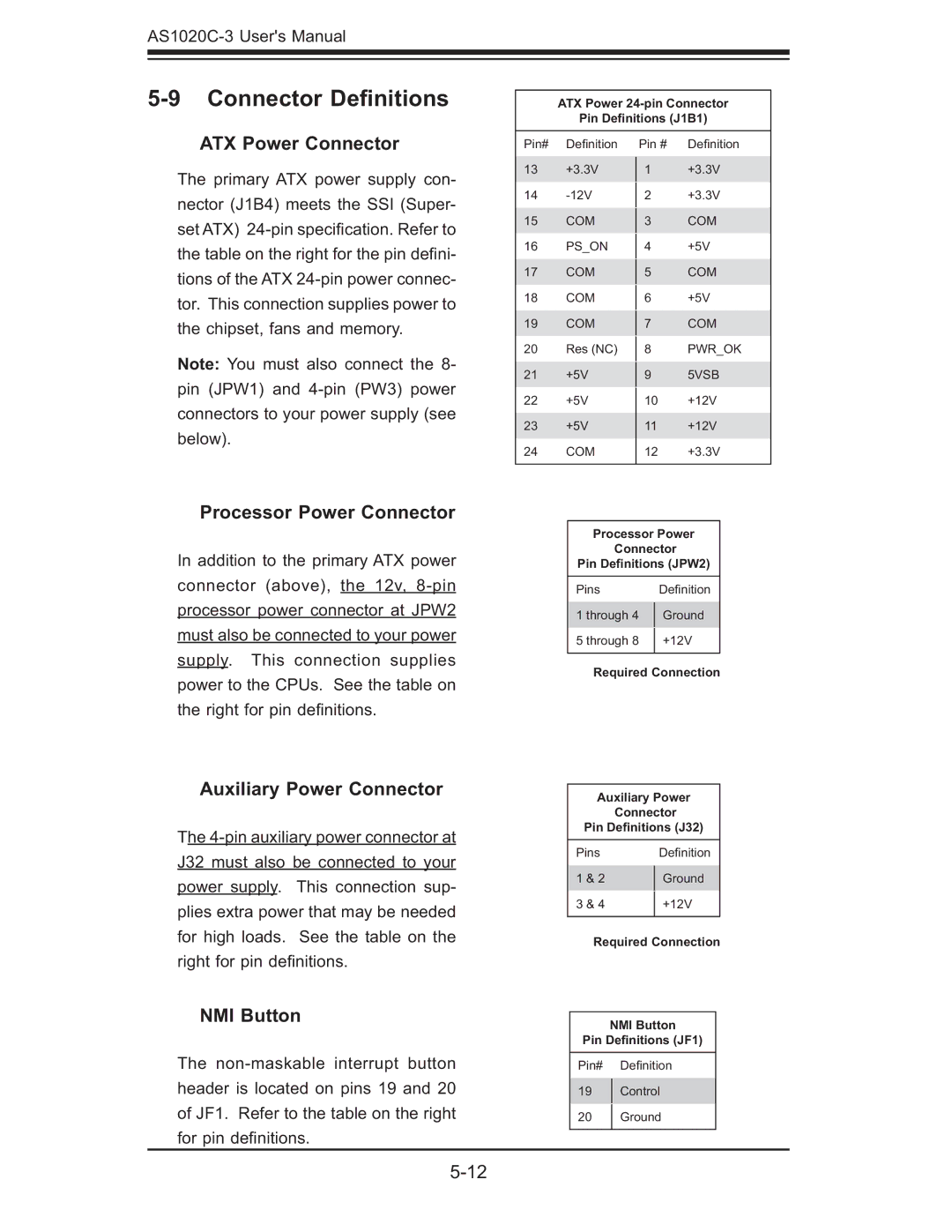
ATX Power Connector
The primary ATX power supply con- nector (J1B4) meets the SSI (Super- set ATX)
Note: You must also connect the 8- pin (JPW1) and
ATX Power
Pin Definitions (J1B1)
Pin# | Defi nition | Pin # | Defi nition | |
13 | +3.3V | 1 | +3.3V | |
14 |
| +3.3V | ||
2 | ||||
15 | COM |
| COM | |
3 | ||||
16 | PS_ON |
| +5V | |
4 | ||||
17 | COM |
| COM | |
5 | ||||
18 | COM |
| +5V | |
6 | ||||
19 | COM |
| COM | |
7 | ||||
20 | Res (NC) |
| PWR_OK | |
8 | ||||
21 | +5V |
| 5VSB | |
9 | ||||
22 | +5V | 10 | +12V | |
23 | +5V | 11 | +12V | |
24 | COM | 12 | +3.3V | |
|
|
|
|
Processor Power Connector
In addition to the primary ATX power connector (above), the 12v,
Auxiliary Power Connector
The
NMI Button
The
Processor Power
Connector
Pin Definitions (JPW2)
Pins | Defi nition | |
1 through 4 | Ground | |
5 through 8 | +12V | |
|
|
Required Connection
Auxiliary Power
Connector
Pin Definitions (J32)
Pins | Defi nition | |
1 & 2 | Ground | |
3 & 4 | +12V | |
|
|
Required Connection
NMI Button
Pin Definitions (JF1)
Pin# Defi nition
19Control
20Ground