Chapter 1: Introduction
Cooling System
The
A fan speed control setting in BIOS allows chassis fan speed to be determined by system temperature [recommended setting is
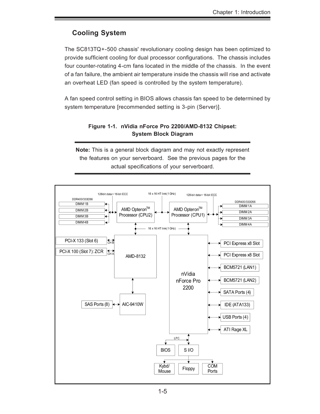
Figure 1-1. nVidia nForce Pro 2200/AMD-8132 Chipset:
System Block Diagram
Note: This is a general block diagram and may not exactly represent the features on your serverboard. See the previous pages for the actual specifi cations of your serverboard.
16 x 16 HT link(1 GHz) |
| ||||||
DDR400/333/266 |
|
|
|
|
|
| DDR400/333/266 |
DIMM 1B |
|
|
|
|
|
| |
| AMD OpteronTM | AMD OpteronTM |
| DIMM 1A | |||
DIMM 2B |
|
| |||||
|
| DIMM 2A | |||||
DIMM 3B |
| Processor (CPU2) | Processor (CPU1) |
| |||
|
| DIMM 3A | |||||
DIMM 4B |
|
|
|
|
|
| |
|
|
|
|
|
| DIMM 4A | |
|
|
| 16 x 16 HT link(1 GHz) |
|
| ||
|
|
|
|
|
| ||
CH B |
|
|
|
|
| PCI Express x8 Slot | |
|
|
|
|
|
| ||
CH A |
|
|
|
| PCI Express x8 Slot | ||
|
|
|
|
|
| ||
|
|
|
|
| nVidia |
| BCM5721 (LAN1) |
|
|
|
|
|
|
| |
|
|
|
|
| nForce Pro |
| BCM5721 (LAN2) |
|
|
|
|
| 2200 |
| SATA Ports (4) |
|
|
|
|
|
|
| |
SAS Ports (8) |
|
|
|
| IDE (ATA133) | ||
|
|
|
|
|
|
| USB Ports (4) |
|
|
|
|
|
|
| ATI Rage XL |
|
|
|
| LPC |
|
| |
|
|
| BIOS |
| S I/O |
|
|
|
|
| Kybd/ |
| Floppy | COM |
|
|
|
| Mouse |
| Ports |
| |
|
|
|
|
|
| ||
|
|
|
|
|
|
| |