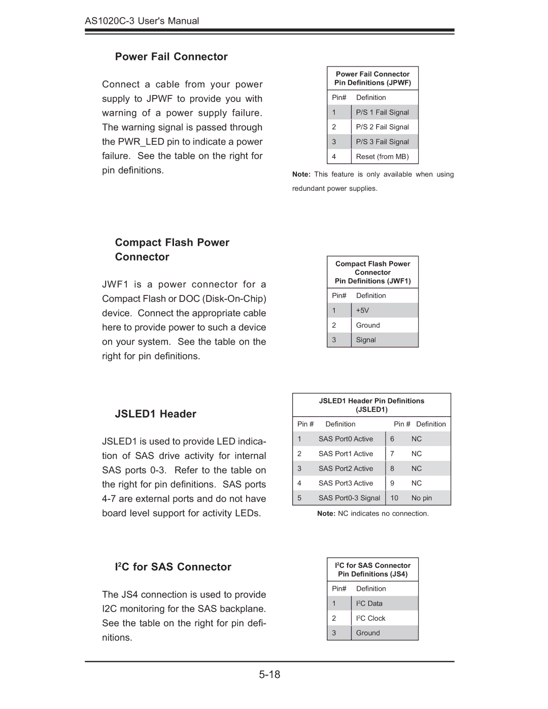
Power Fail Connector
Connect a cable from your power supply to JPWF to provide you with warning of a power supply failure. The warning signal is passed through the PWR_LED pin to indicate a power failure. See the table on the right for pin defi nitions.
Power Fail Connector
Pin Definitions (JPWF)
Pin# Defi nition
1P/S 1 Fail Signal
2 P/S 2 Fail Signal
3 P/S 3 Fail Signal
4 Reset (from MB)
Note: This feature is only available when using redundant power supplies.
Compact Flash Power
Connector
JWF1 is a power connector for a Compact Flash or DOC
JSLED1 Header
Compact Flash Power
Connector
Pin Definitions (JWF1)
Pin# Defi nition
1+5V
2Ground
3Signal
JSLED1 Header Pin Definitions
(JSLED1)
JSLED1 is used to provide LED indica- tion of SAS drive activity for internal SAS ports
Pin # Defi nition
1SAS Port0 Active
2SAS Port1 Active
3SAS Port2 Active
4SAS Port3 Active
5SAS
Pin # Defi nition
6NC
7NC
8NC
9NC
10 No pin
board level support for activity LEDs.
I2C for SAS Connector
The JS4 connection is used to provide I2C monitoring for the SAS backplane. See the table on the right for pin defi - nitions.
Note: NC indicates no connection.
I2C for SAS Connector
Pin Definitions (JS4)
Pin# Defi nition
1I2C Data
2I2C Clock
3Ground